8
2 MAIN MENU
2.1 GENERAL MONITOR
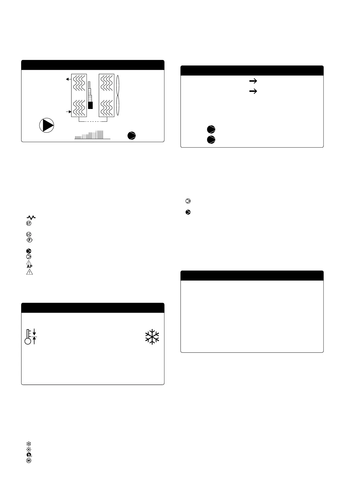
This mask is used to display the unit's general status:
9.8°C
15.0°C
EV CN
100
1
— Current date and time
— Evaporator (EV) output temperature;
— Evaporator (EV) input temperature; when it is just below the value relative to
the evaporator input temperature, the icon of the currently active pump will
appear (with the relative number);
— Percentage of power (displayed graphically with a bar to the right of the evapo-
rator) requested by the system;
— Fan speed; percentage value displayed to the right of the condenser;
— Inverter compressor speed; value displayed as a percentage by a graphic bar
below the heat exchangers;
NB: some icons can appear at the bottom of this window, indicating cer-
tain system states:
— : anti-freeze heater activation;
— : Indicates that low output temperature anti-freeze prevention is active
(turns o the compressors)
— : indicates that the low charge function is active;
— : Indicates that the ow switch is open. The compressors are turned o and
the pumps release the ow switch
— : indicates that the compressor is on;
— : indicates that the compressor is o;
— : indicates a compressor alarm;
—
: Indicates that high pressure capacity control is active;
2.2 SYSTEM MONITOR
This mask is used to display the system's general status:
37.0°C
100.0% 15.0%
84.7%100.0%
5.0°C
7.0°C
Setpoint
Di.
Outlet Temp.:
Ep Ei
Att:Req.:
— Current working setpoint;
— Current working dierential;
— Temperature probe for machine regulation;
— If a PI function is active, also the proportional factor “Ep” and the integral factor
“Ei” will be displayed;
— Requested percentage of power and percentage of power actually active on
the system side;
NB: some icons can appear in the window, indicating certain system
states:
—
: system chilled water production;
—
: system hot water production;
—
: time bands active;
— : multifunction input;
2.3 CIRCUIT MONITORS
This mask is used to display the cooling circuit's general status; if the unit has mul-
tiple circuits, each will have a dedicated window:
23.1bar 39.5°C
6.4bar -2.6°C
14.8°C
80.8°C
50.0°C
CP1: 0s
CP2: 0s
AP: Tc:
BP: Te:
T. Liquid.:
Discharge Temp.
T. Gas Prem. 2:
— AP: high pressure
— BP: low pressure
— Tc: condensation temperature
— Te: evaporating temperature
— T.Liquid: liquid temperature
— T.discharge gas: inverter compressor discharge gas temperature
— T.discharge gas 2: ON/OFF compressor discharge gas temperature
The status of the compressors can be:
— : indicates that the compressor is o, the (remaining) time to satisfy the min-
imum OFF time is indicated to the side;
— : indicates that the compressor is on, the (remaining) time to satisfy the min-
imum ON time is indicated to the side;
NB: if the card is restarted, there will be a 60 second wait to guarantee
the minimum shut-o time necessary for the inverter compressor driv-
er.
2.4 POWER DEMAND MONITOR
This mask is used to display the data related to the power demand on the indicated
circuit; if the unit has multiple circuits, each will have a dedicated window:
100.0%
84.7%
4500rpm
4000rpm
Inverter speed:
Needed speed:
Circuit 1:
Total require
Circuit 1
— Total thermostat request;
— Power delivered by circuit 1;
— Calculated speed (in rpm) for satisfying the thermostatic request at the current
operating conditions;
— Current speed of the inverter compressor (in rpm);
2.5 MASTER UNIT MONITOR
NB: this mask is only available on the Master unit, if the system has a
Master/Slave conguration with multiple units.
This mask is used to display the data related to the system's total power demand
and the relative power percentages divided among the units connected to the sys-
tem: