9
---°C
100.0%
100.0%
100.0%Circuit 2:
Circuit 1:
Total require
Common Outlet:
— Common output (optional): probe water temperature on the common output
of the two master and slave unit outputs;
— Demand: power calculated by the Master unit thermostat that will be distribut-
ed between the two units;
— Unit 1: percentage power requested of the Master unit;
— Unit 2: percentage power requested of the Slave unit;
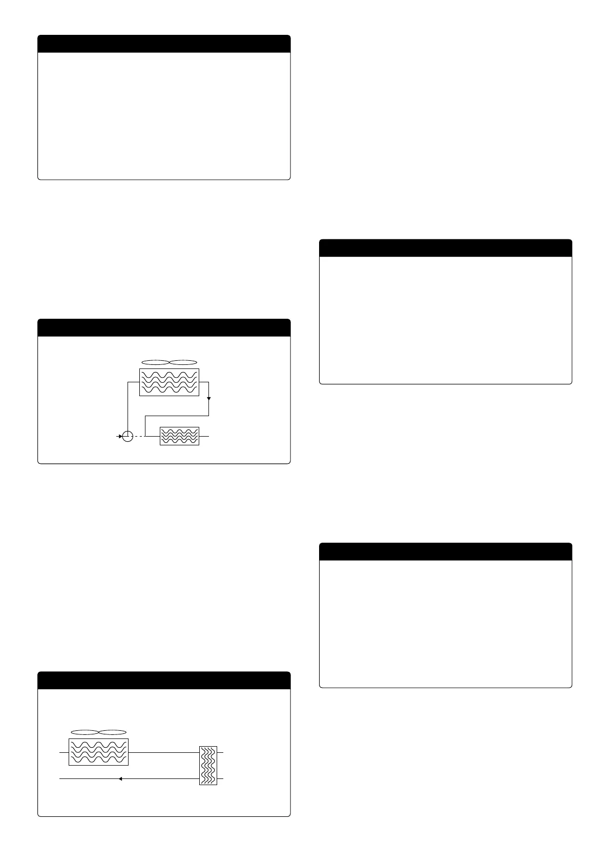
2.6 FREE COOLING MONITOR
WARNING: this mask is available on free cooling units.
This mask is used to display the status of the free cooling circuit:
FC
38%
14.2°C 10.0°C
0/092%
15.0°C
Potenza FC:
Tot:
— Activation of the 3-way valve with the display of moving arrows for pump status
and water circulation;
— Power delivered by the free cooling based on that available;
— Operating status;
— Tot: total power as a percentage delivered by the unit. If only free cooling, corre-
sponds to the total power delivered by free cooling, if mixed operation the total
power is the sum of the power delivered by free cooling and the compressors;
— Display of the values of the free cooling input (lower left), evaporator input (if FC
on, upper right) and evaporator output (lower right) probes;
Possible operating status:
— OFF (unit o );
— FC (unit only operating in free cooling);
— FC+CP (unit in mixed operation);
— CP (unit operating with compressors only);
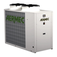
2.7 GLYCOLFREE MONITOR
WARNING: this mask is available on glycolfree units.
This mask is used to display the status of the glycolfree circuit:
FC
41/094%
41%
14.7°C
14.2°C
14.1°C
15.0°C
Potenza FC:
Totale:
— Activation of the branch containing glycol with the display of moving arrows for
pump status and water circulation;
— Power delivered by the free cooling based on that available;
— Tot: total power as a percentage delivered by the unit. If only free cooling, corre-
sponds to the total power delivered by free cooling, if mixed operation the total
power is the sum of the power delivered by free cooling and the compressors;
— Display of the values of the free cooling output (upper left), free cooling input
(lower left), intermediate evaporator (upper right) and evaporator input (lower
right) probes;
— Operating status;
Possible operating status:
— OFF (unit o );
— FC (unit only operating in free cooling);
— FC+CP (unit in mixed operation);
— CP (unit operating with compressors only);
2.8 TOTAL RECOVERY MONITOR
WARNING: this mask is available on units with total recovery.
This mask is used to display the status of the total recovery:
42.2°C
43.8°C
0%
Ingresso acqua:
Uscita acqua:
O generale
Richiesta:
— Display of the water temperature value of the total recovery input probe;
— Display of the water temperature value of the total recovery output probe;
Total recovery status:
— ow switch open (water is not circulating in the hydraulic circuit of the recovery
system and therefore it is disabled);
— enabled (water is circulating in the hydraulic circuit of the recovery system and
therefore it is enabled);
— general o (the whole unit is in stand-by), o from the display (general disa-
bling of the unit from the pGD1 button);
2.9 PEC PRESSURE CONTROL MONITOR
This mask is used to display the result of the control on the machine pressure delta,
controlled by the PEC card:
:
in progress...
Pressure delta control
PEC
If the result of the pressure delta control is greater than 15 bar (and the 4-way must
switch), the valves must be controlled without the activation of the compressors to
reduce the pressure delta; Alarms (warnings) are not generated in this situation).
If the control is less than 3 bar (hot/cold operation or a 4-way must switch), the
compressors are started without the valve control in order to create the pressure
delta; after 300s in this situation an alarm is generated with a machine block.