2-38 Subject to Export Control, see Cover Page for details.
B. Generator Calibration (cont)
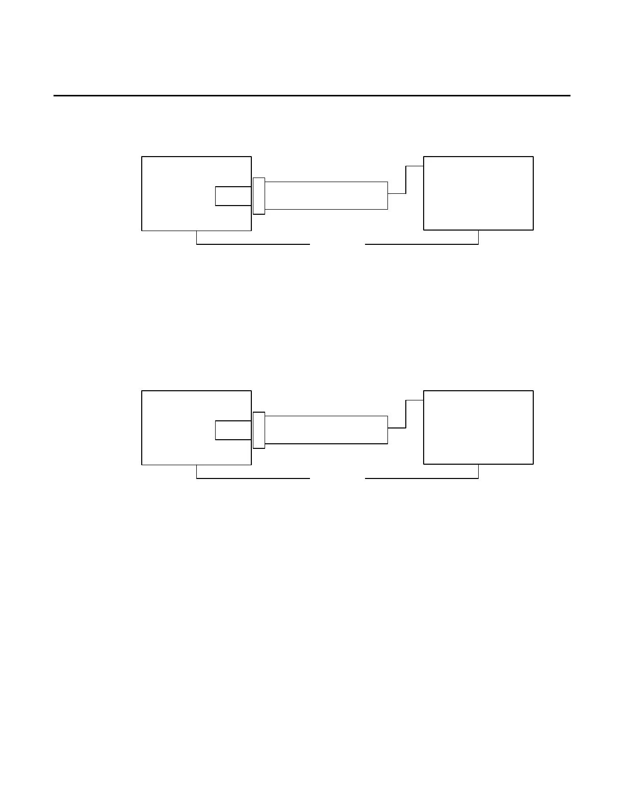
ANT CONNECTOR
10. Establish the following test setup:
Test*Set
ANT
Power*Meter*Sensor
Power*Meter
Channel*A
Ethernet
( *Only*required*for* AU T O* Mode*)
11. Press the F3 “CAL” Key.
12. Press the F1 “ANT” Key and follow the instructions on the screen to calibrate the UUT ANT
Port.
13. When the message “CALIBRATION COMPLETED” appears, press the F1 “Enter” Key to
display the Generator Calibration Screen.
SWR CONNECTOR
14. Establish the following test setup:
Test*Set
SWR
Power*Meter*Sensor
Power*Meter
Channel*A
Ethernet
( *Only*required*for* AU T O* Mode*)
15. Press the F3 “CAL” Key.
16. Press the F3 “SWR” Key and follow the instructions on the screen to calibrate the UUT
SWR Port.
17. When the message “CALIBRATION COMPLETED” appears, press the F5 “Enter” Key to
display the Generator Calibration Screen.
18. Cycle power on the Test Set.