Subject to Export Control, see Cover Page for details. 2-39
C. Receiver Calibration
TEST EQUIPMENT: Power Meter
Power Meter Sensor
Power Splitter (2-Way Resistive)
1. With the System Menu displayed, press the F4 “Selftest” Key to display the Self Test
Menu.
2. Press the 3 Key to display the Calibration Screen.
3. Enter the Calibration Password (30203). Press the F1 “Done” Key to display the Internal
Calibration Menu.
4. Press the 8 Key (REC CAL AUTO) to display the Receiver Calibration Screen.
5. With the cursor on the Mode field, set the Mode selection based on the Power Meter used:
AUTO Agilent N1911A Power Meter / Agilent E4412 Power Sensor
MANUAL Other Power Meter / Power Meter Sensor.
ANT CONNECTOR
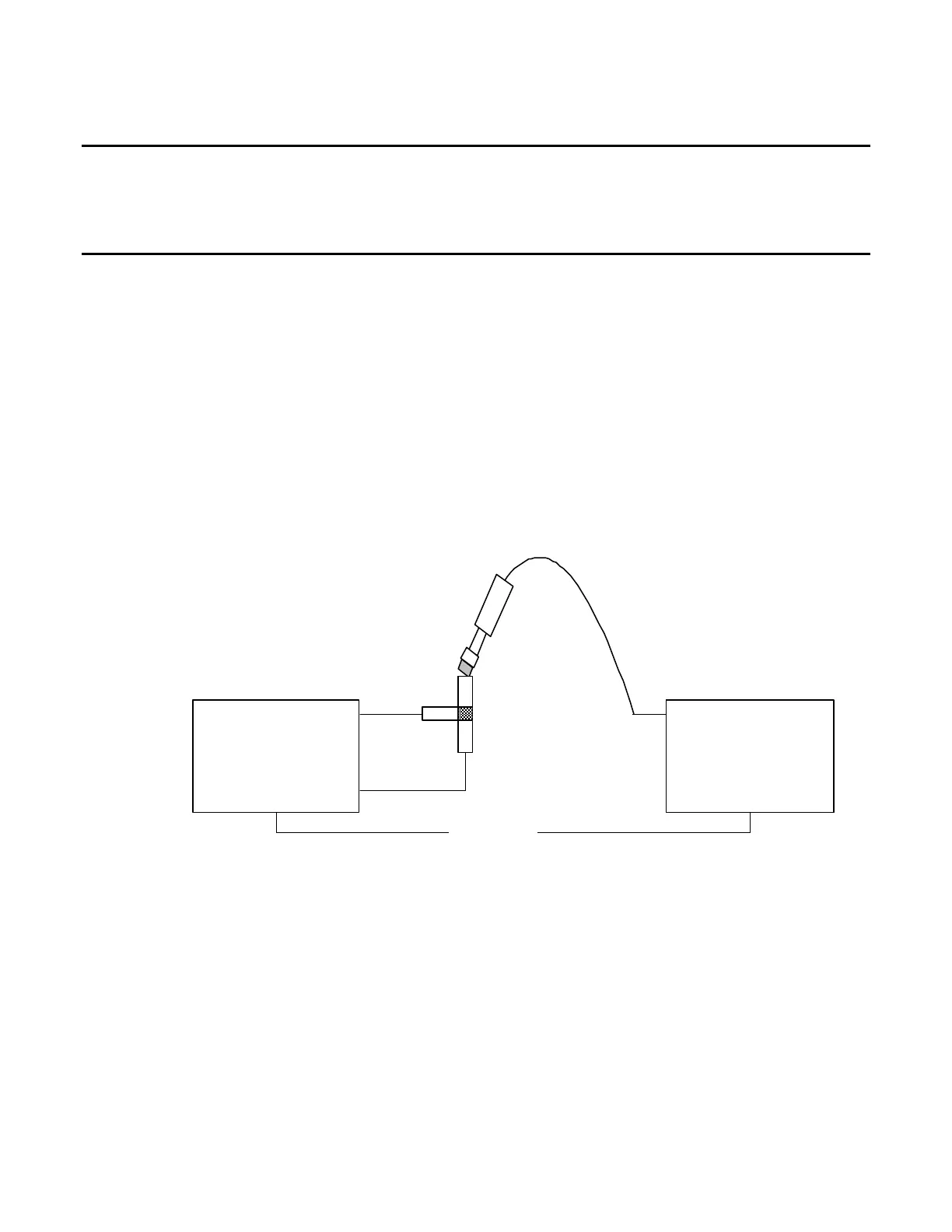
6. Establish the following test setup:
SWR
ANT
Test*Set
Power*Meter
Channel*A
Ethernet
(* Only*required* for* AU T O*Mode*)
Power*Meter*Sensor
Power
Splitter
7. Press the F3 “CAL” Key.
8. Press the F1 “ANT” Key and follow the instructions on the screen to calibrate the UUT ANT
Port.
In MANUAL Mode the Test Set prompts the user to enter readings from the Power Meter.
NOTE
This is an interactive process. At each frequency the output level is
adjusted based upon the Power Meter reading entered by the user until
the reading is within acceptable limits.