2-40 Subject to Export Control, see Cover Page for details.
C. Receiver Calibration (cont)
9. When the message “CALIBRATION COMPLETED” appears, press the F5 “Enter” Key to
display the Receiver Calibration Screen.
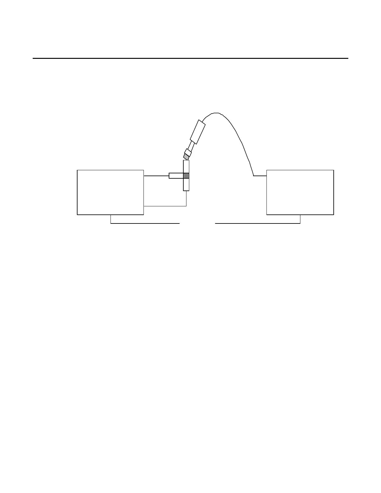
T/R CONNECTOR
10. Establish the following test setup:
SWR
T/R
Test*Set
Power*Meter
Channel*A
Etherne t
Power
Splitter
( *Only*required* for* AU TO*Mode* )
Power*Meter*Sensor
11. Press the F3 “CAL” Key.
12. Press the F2 “T/R” Key and follow the instructions on the screen to calibrate the UUT T/R
Port.
13. When the message “CALIBRATION COMPLETED” appears, press the F5 “Enter” Key to
display the Receiver Calibration Screen.
PRE AMP
14. Press the F3 “CAL” Key.
15. Press the F3 “AMP” Key and follow the instructions on the screen.
16. When the message “CALIBRATION COMPLETED” appears, press the F5 “Enter” Key to
display the Receiver Calibration Screen.
17. Cycle power on the Test Set.
18. With the System Menu displayed, press the F4 “Selftest” Key to display the Self Test
Menu.
19. Press the 3 Key to display the Calibration Screen.
20. Enter the Calibration Password (30203). Press the F1 “Done” Key to display the Internal
Calibration Menu.
21. Press the 8 Key (REC CAL AUTO) to display the Receiver Calibration Screen.
22. Press the F4 “Pre Norm” Key to to normalize the UUT Receiver.
23. Verify Normalize Numbers are within acceptable range of -15 to -10.
24. Cycle power on the Test Set.