GES – Users Manual
Page 29 of 33
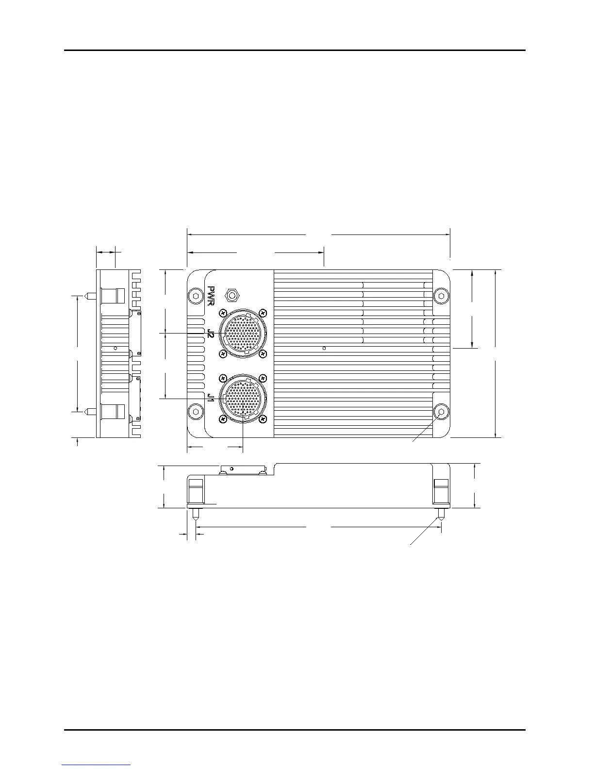
9. Hardware Mounting
The GES weighs 2 pounds 12 ounces and is mounted via its four 10-32 captive screws.
The recommended clearance for the mounting hardware below the mounting surface is
0.750”. The GES mounting screws extend 0.665” below the bottom of the chassis.
Previous versions of the GES had shorter mounting screws. The current (longer) screws
can be easily recognized because they are Allen head screws with a black oxide coating.
The rectangular mounting pattern for the attachment points is 3.55” x 7.71” as shown in
Figure 9-1. The overall external dimensions are 8.25” L x 5.15” W x 1.38” H.
Figure 9-1: External Dimensions
The Center of Gravity (CG) is also shown in Figure 9-1. It is indicated by the letters “CG”
before the dimension.
10. Indicators
The GES has one green LED on the front panel labeled PWR.
This LED is illuminated when input power is applied to the GES.
5.15
CG 2.40
CG 4.30
CG 0.60
5/32
HEX (4 PLACES)
10-32 2A NF THREAD (4 PLACES)
3/4" MIN. DEPTH
8.25
7.71
0.27
1.38
1.31
1.75
2.00
1.95
3.55
0.80