GES – Users Manual
Page 2 of 33
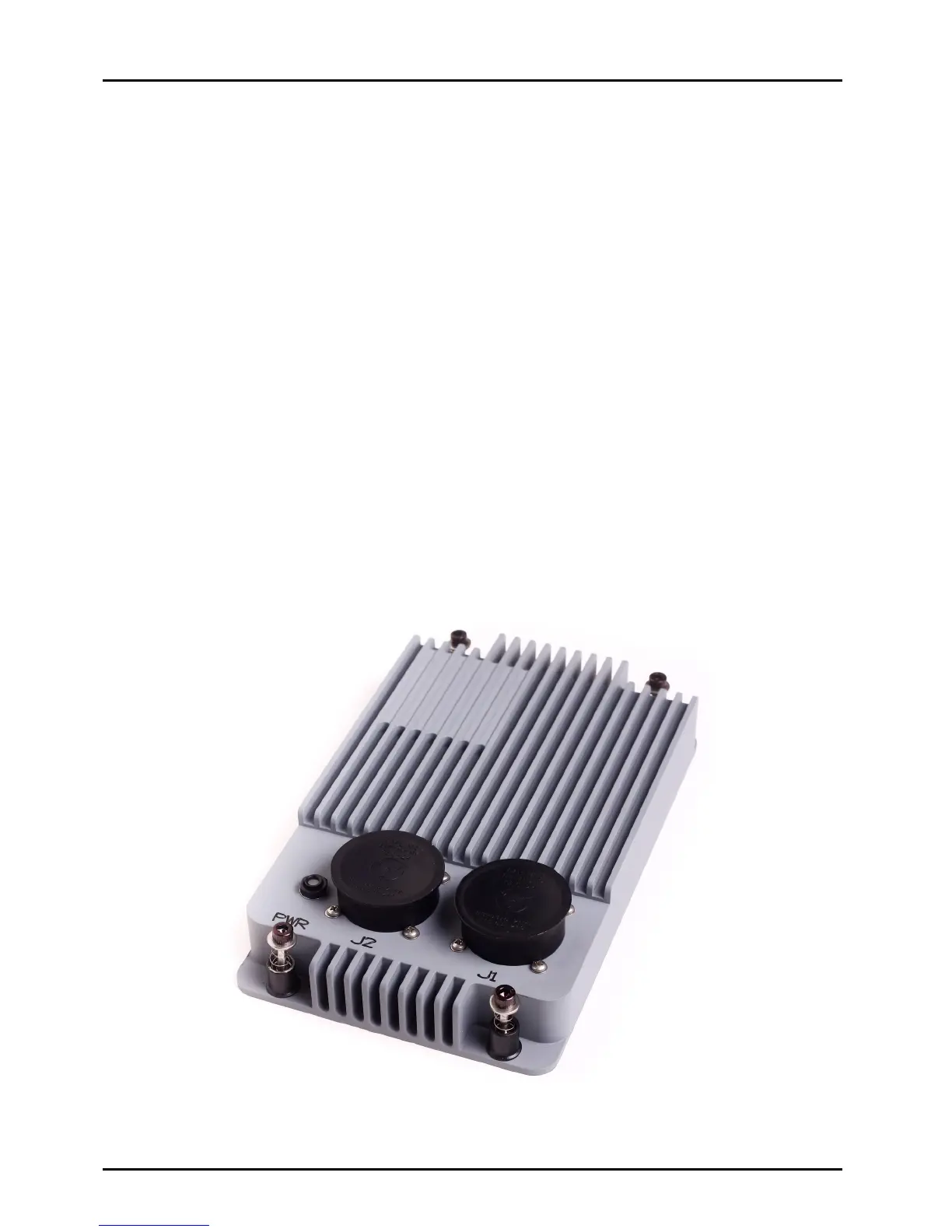
3. Electrical Connections
The GES has two electrical connectors, J1 and J2.
3.1. J1 Connector
J1 is a 100 pin M38999 Series II connector, Part Number MS27508E22B35P.
An example mating cable connector for J1 is Part Number MS27473E22B35S.
J1 contains the following electrical interfaces:
• Six Ethernet Ports (0 – 5)
• Two RS-232 Serial Ports
o DEV1 – Dedicated Maintenance Port for the Management Processor
o DEV2 – Designed to be programmed as an Ethernet to Serial Bridge
3.2. J2 Connector
J2 is a 100 pin M38999 Series II connector Part Number MS27508E22B35PA.
An example mating cable connector for J2 is Part Number MS27473E22B35SA.
J2 contains the following electrical interfaces:
• Six Ethernet Ports (6 – 11)
• Input Power (nominal 28 VDC per MIL-STD-704A)