GES – Users Manual
Page 4 of 33
3.4. Interface Port Details
3.4.1. Ethernet Ports
All connections in Table 3-1 that have a white background are Ethernet Port
connections.
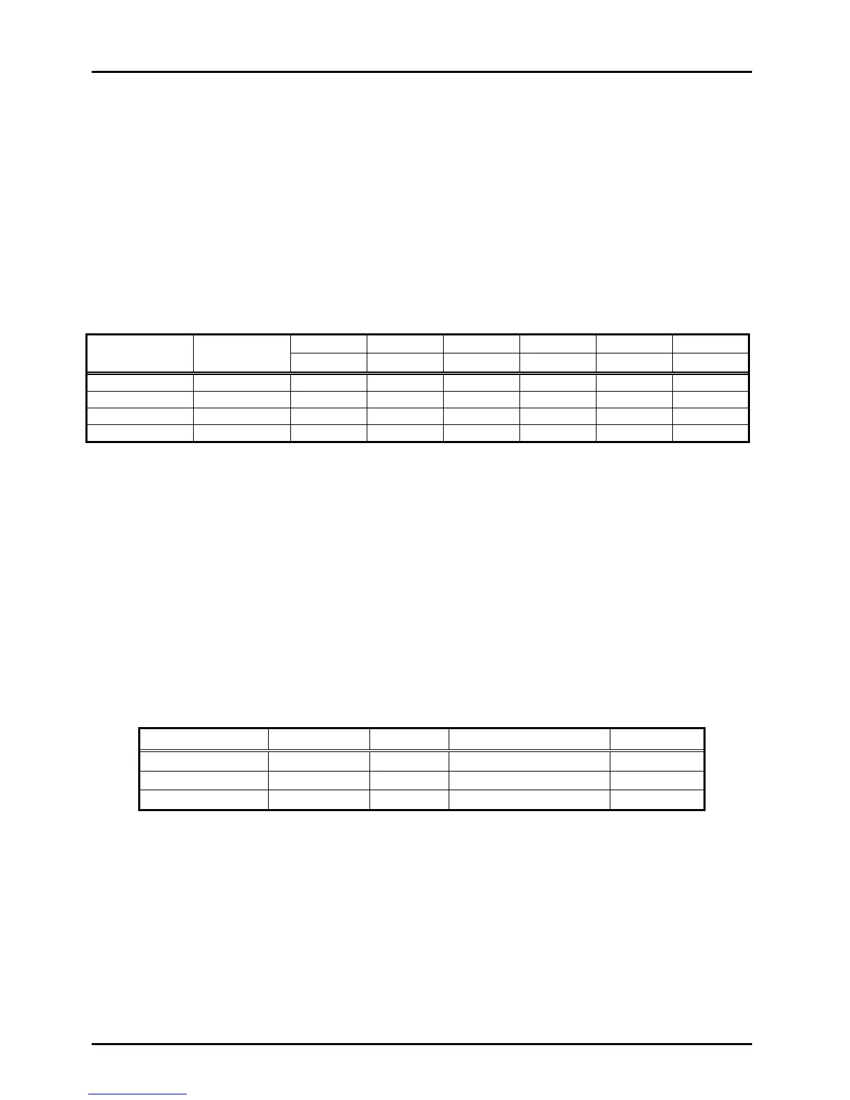
Table 3-2 indicates the appropriate wiring connections for the GES Ethernet ports
relative to the available link speeds. Please note that MDI is the preferred connection
choice. The GES and most modern Ethernet enabled electronics are capable of
connecting using the MDIX scheme, but it is not advised.
Table 3-2: Ethernet Port Connections
GES Pin
RJ-45
Pinout P/N
3.4.2. Serial and Programming Ports
All connections in Table 3-1 that have an Orange background are Serial Port
connections.
The DEV1 serial port is a dedicated GES Management Processor Maintenance Port.
The DEV2 serial port was designed for future expansion as an in-band Ethernet to Serial
Bridge.
Table 3-3 indicates the appropriate wiring connections for the DEV1 and DEV2 serial
ports.
Table 3-3: Serial Port Connections
3.4.3. Management Processor
The GES provides an ARM 9 processor running at 96MHz for both internal and customer
specified functions. This processor is in-band allowing control by any device on the
Ethernet network that is connected to the GES.
This processor is lightly loaded after initialization of the GES allowing customer specified
functions to use most of the available processing power if required.