27
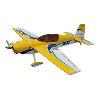
11. Attach the ball links and brass spacers to the
rudder servo arm and then attach the servo arm
to the rudder servo as shown.
12. Plug the rudder servo into the rudder channel of
the receiver and power up. Turn on transmitter
to center rudder servo. Ensure servo trim and
sub trims are centered.
Note: On metal geared servos use Loctite for all
Servo arm mounting screws.
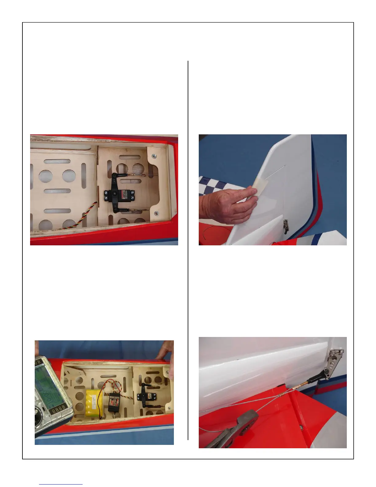
13. Tape the rudder balance tab to the top leading
edge of the vertical fin in the neutral position as
shown. This ensures the rudder is straight when
the cables are attached.
14. Screw threaded couplers half way into ball links.
Attach ball link to rudder control horn on both
sides of the rudder. Thread the rudder cable
through a brass swage tube, then the threaded
coupler, and back through the brass swage tube
on both sides. Pull with light tension on the ca-
ble through the coupler on both sides as shown.
The loop through the coupler should be approxi-
mately 1/2” long.