13
Aileron Control Linkage Installation
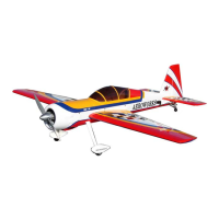
1. Gather the aileron control linkage parts as shown
below.
1 pushrod
2 4-40 ball link assemblies
1 brass spacer
1 left and 1 right side control horn
6 wood screws
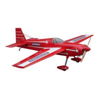
2. Assemble the pushrod and control horn assem-
bly as shown. The ball link goes between the
left and right sides of the control horn sides and
is secured with a nylon lock nut. Start with the
center hole in the control horn. The ball link
may be moved up or down for more or less con-
trol throw. Brass spacer goes between servo arm
and ball link.
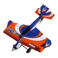
3. Place the control horns over the predrilled
mounting holes.
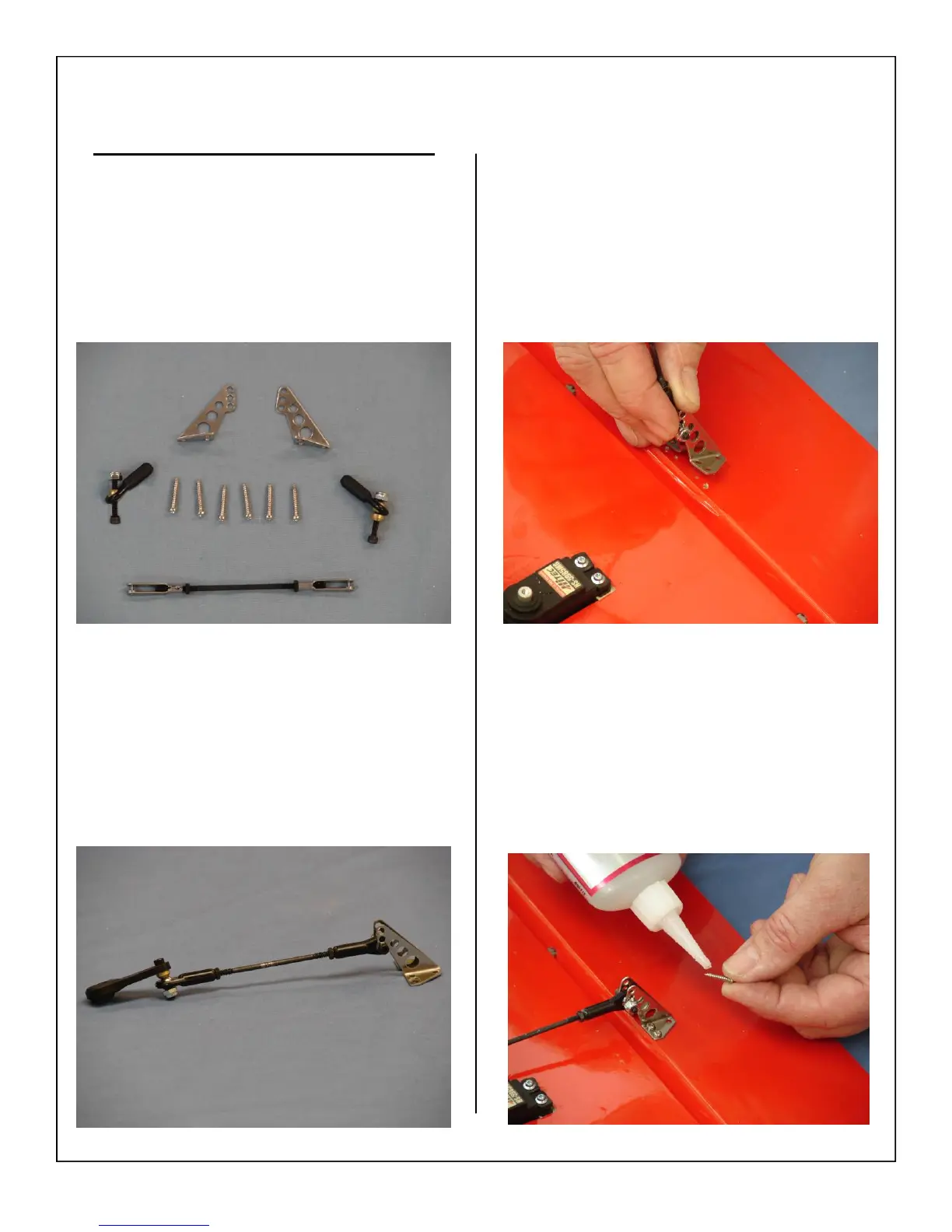
4. Use a drop of thick CA glue on each screw as
shown.