10 / 34
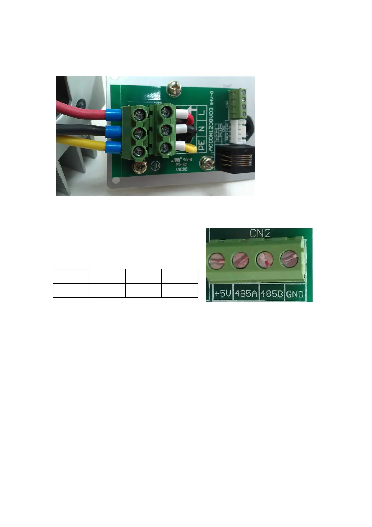
According to polarities, connect the grounding line to PE terminal; the neutral line to
N; and phase line to L. as shown in the following figure.
Communication via RS485(optional):
Only twisted-pair cable (or AB cable) apply to the communication connection.
There are 4 pins for communication connection,
as shown in the figure, and they are defined as
follows:
Pin 1 and pin4 is only used when communication is realized through wireless
communication module.
Connect Pin 2, Pin 3 if communication is realized through RS485.
RS485 can be used for multipoint communication. Up to 31 inverters can
communicate and be monitored through one communication module.
RS485 communication module and receiver can be purchased from Afore New
Energy as options. And relevant monitoring software can be downloaded from
www.aforenergy.com.