DR Detector Calibration|Calibrating the DR Detector|14
XD 10, XD⁺10, XD 14, XD⁺14, XD 17, XD⁺17, XF⁺10, XF⁺14, XF⁺17 Exposure Sequence
Modality Settings
Apply these modality settings:
Table 3: Modality settings
kV 75 kV
mAs (indicative value for
first exposure level)
25 mAs (XD 10, XD⁺10, XF⁺10)
32 mAs (XD 14, XD⁺14, XD 17, XD⁺17, XF⁺14, XF⁺17)
mAs (indicative value for
second exposure level)
12.5 mAs (XD 10, XD⁺10, XF⁺10)
4 mAs (XD 14, XD⁺14, XD 17, XD⁺17, XF⁺14, XF⁺17)
Focus large focus
SID Use the (average) SID for normal operation.
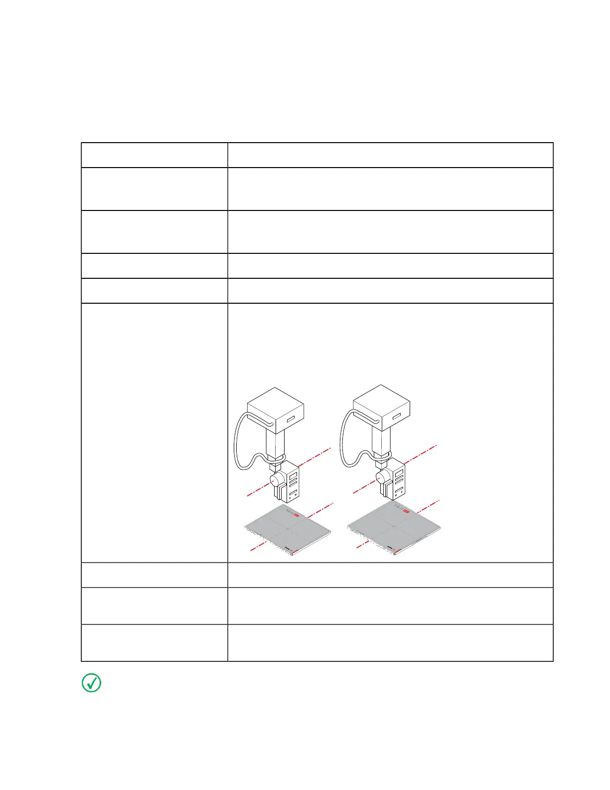
Position If the DR Detector is used in a fixed position, use the same position
for calibration.
If the DR Detector is used in different positions, perform the cali-
bration with the short side of the DR Detector parallel to the axis of
the X-ray tube.
Grid Remove the grid.
Filtration Mount the Agfa calibration filter (Cu 1.5 mm). Check that there is
no additional filtration.
Collimation The collimation area should extend at least 1.5 cm on each side of
the DR Detector.
Note If the exposure settings used for a previous calibration are known, use these settings.
On modalities that support automatic collimation, the collimation settings are applied automatical-
ly and must be checked by the user.
0134KEN20240524 1323