Installation
26 Agilent 5100 and 5110 ICP-OES User’s Guide
Agilent ICP-OES Instrument Overview
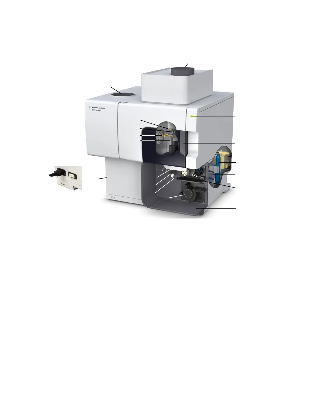
Figure 1. Front and side of the ICP-OES instrument
1. Exhaust 8. Torch loader handle 15. Torch compartment handle
2. Air inlet filter 9. Spray chamber 16. Water assembly
3. Cone and axial pre-optics
window (not shown)
10. Nebulizer 17. Optics purge filter for argon
or nitrogen
4. Snout and radial pre-optics
window (not shown)
11. Peristaltic pump 18. Gas supply assembly
5. Induction coil 12. Mains power switch and
cable connection
19. Optional AVS 4, AVS 6 or
AVS 7 Switching Valve
accessory location
6. Torch 13. Front panel power button 20. Drain for liquid overflow
7. Nebulizer and make up gas
connections
14. LED instrument status
indicator
11
7
9
10
8
1
14
2
5
3
18
15
16
17
6
13
12
20
4
19