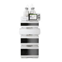
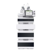
Do you have a question about the Agilent Technologies 1220 Infinity II LC and is the answer not in the manual?
Describes the different available configurations of the 1220 Infinity II LC system.
Details the configurations available for the 1220 Infinity II LC VL system.
Explains the Early Maintenance Feedback (EMF) system for proactive component monitoring.
Outlines environmental conditions and site preparation needed for instrument installation and operation.
Lists the physical dimensions, weight, and power requirements of the LC system.
Details the performance characteristics of the LC system's various components.
Instructions for unpacking the LC system and checking the delivery contents.
Step-by-step guide for physically installing the LC system hardware components.
Procedures for connecting the LC system to the data system and initial software configuration.
Steps for performing installation checks, priming, and checkout runs for system verification.
Details on setting up IP address, subnet mask, and default gateway for network connectivity.
Explains how to select the initialization mode for determining TCP/IP parameters.
Information on using DHCP for automatic IP address assignment and network setup.
Describes how to use BootP for automatic IP address assignment and network configuration.
Provides a general overview of the solvent delivery system's design and function.
Explains the function and operation of the built-in online degasser.
Details the mechanical principles behind the pump's operation and solvent delivery.
Explains the feature that optimizes flow stability based on solvent compressibility.
Describes the operation and components of the manual injector.
Details the functionality, sample racks, and transport mechanism of the autosampler.
Outlines the step-by-step process the autosampler follows for sample injection.
Explains the flow path and valve positions during the injection sequence.
Describes the operational principles, temperature range, and column capacity of the column oven.
Introduces the two main detector types available: VWD and DAD.
Details the features and performance of the VWD detector.
Explains the features, optical system, and specifications of the DAD detector.
Provides recommendations for selecting the appropriate flow cell based on column specifications.
Describes tests for the overall LC system, including installation checks and module status.
Details tests for the pump, including leak tests and pressure checks.
Covers maintenance positions, injector steps, and alignment procedures for the autosampler.
Explains tests for the VWD and DAD detectors, including cell, lamp, and wavelength checks.
Lists and explains generic error messages applicable to all HPLC modules.
Details specific error messages related to the pump's operation and components.
Lists and explains error messages related to the autosampler's mechanics and operation.
Covers error messages specific to the VWD and DAD detectors.
Procedures for maintaining and repairing the solvent delivery system components.
Steps for flushing and exchanging seals for the manual injector.
Procedures for maintaining and repairing the autosampler's major assemblies.
Simple maintenance and repair procedures for the VWD and DAD detectors.
Lists part numbers and descriptions for the main LC system components.
Details parts for the solvent delivery system, including pump and degasser components.
Lists parts for the manual injector and autosampler, including assemblies and sample loops.
Provides part numbers for VWD and DAD detectors, including lamps and flow cells.
Instructions for installing the optional oven upgrade kit.
Steps for installing an optional external tray for the autosampler.
Procedures for installing the Active Inlet Valve upgrade kit.
Provides a general overview and categorization of various system cables.
Details analog cables used for connecting modules to integrators or converters.
Information on remote cables used for connecting Agilent modules to integrators.
Describes CAN and LAN cables used for module-to-module and module-to-PC communication.
General safety precautions and guidelines for operating the instrument.
Explanation of safety symbols used throughout the manual and their meanings.
Recommendations for using solvents, including flow cell compatibility and corrosive properties.
Information on how to find the latest product and service details on the Agilent website.
| Flow Rate Precision | < 0.07 % RSD |
|---|---|
| Wavelength Accuracy (VWD) | ± 1 nm |
| Data Acquisition Rate | Up to 80 Hz |
| Data Sampling Rate | Up to 80 Hz |
| Flow Rate Range | 0.001 to 5 mL/min |
| Pressure Range | 0 to 600 bar (8700 psi) |
| Wavelength Range | 190 to 600 nm (VWD) |
| Detector Type | Variable Wavelength Detector (VWD) |
| Injection Volume | 0.1 to 100 µL |
| Flow Rate Accuracy | ±1% or ±0.5 µL/min, whichever is greater |
| Column Temperature Stability | ±0.1°C |


