If activity is not detected, check A3U17 (Pin 2). If Pin 2 is at a TTL-high level or changing states, then either the
laser head is not tuned properly, the Reference Receiver is failing, or the Reference Receiver is not receiving
adequate signal. Verify laser tuning using step c before continuing with step d. If A3U17 (Pin 2) is at a TTL-low
level and there is no output activity as described above, then A3U17 may be bad or it's output may be shorted. Go to
step d.
a. Align an HP 10780 Receiver so that the laser beam is incident on the photodiode lens. If the laser
head is properly tuned, the LED on top of the HP 10780 should light and the 10780 should output a
square wave. This test can be performed with the laser head installed in a system using one of the
system axis' receivers. In this case, if the axis interferometer is installed, vibration (etc.) will
modulate the REFerence frequency but a frequency in the range of 1.5 to 2.0 MHz should still be
present, if a steady REFerence frequency signal is not detected by the HP 10780 Receiver, then a
laser tuning failure is indicated which is independent of the Reference Receiver. See HP 5517B
Trouble Isolation Procedure, paragraph 8-74. Otherwise proceed with step d.
b. Measure and record the DC voltages at A3U17 (Pin 10) and the A3R5-R46 node. With -REF ON
jumper still set to LO, place a piece of paper between the A5 Laser Tube Assembly and the A6
Sampler Assembly to block the I aser beam. The voltage at U17 (Pin 10) should drop by 250 mV or
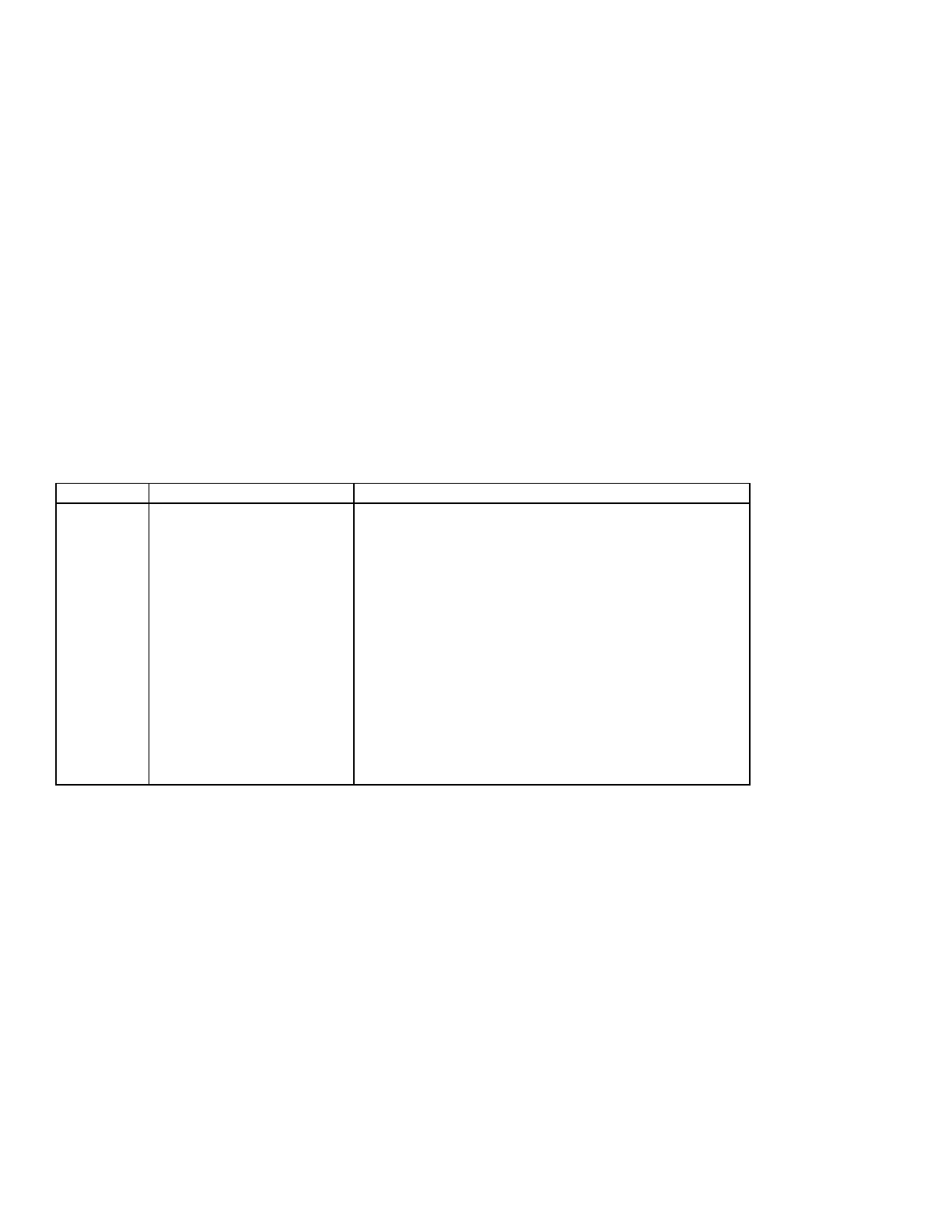
more, indicating adequate signal, and the DC voltages listed in
Table 8-6
should be measured on
the pins of A3U17 with the beam blocked:
Table 8-6. A3U17 Reference Receiver Test Voltages
-15V External Power Source, +5 Volt Regulator
(A3U7).
A3U17, A3U1F, A3U3B, or Digital Circuits
A3CR5,A3U17, or associated passive components.
+0.7 Vdc ±0.1 V [2 mV p-p
noise (nominal)]
A3U17, or associated passive components (A3R43,
A3R44, A3C23 etc.).
If any voltage listed in
Table 8-6
is incorrect, check or replace the part listed. If the voltage at Pin 10 does
not drop to the level listed above, measure the DC voltage at the A3CR5-R46 node with the beam
blocked. It should be approximately 15 Volts and should have increased at least 6 mV above the value
measured and recorded previously when the laser beam was unblocked. If not, check A3R46, C27, or
CR5. A3CR5 can be checked by removing power from the HP 5517B and checking for diode action using a
DC ohmmeter. Resistance measured in the reverse direction should be much larger than the resistance
measured in the forward direction. If A3CR5 is OK, replace A3U17.
e. In cases of marginal signal strength, the following factors should be checked:
• A5 Laser Tube Assembly output power
• A6 Sampler Assembly function
The laser tube assembly output power should be checked according to Laser Power Output Test,
paragraph 4-12.
The A6 Sampler Assembly can be checked as follows:

 Loading...


