SECTION I GENERAL INFORMATION
1-1. INTRODUCTION
1-2. This Operating and Service Manual contains information required to install, operate, test, adjust, and service
the Hewlett-Packard Model 5517B/C/D Laser Head. The information in this manual is specific to the HP 5517B/C/D
and supplements other publications available for Hewlett-Packard Laser Transducer products. Laser and Optics
User Manual and the HP 5527B Laser Position Transducer Designer's Guide Manual that describes how to set up,
align, and use the laser system to make interferometer measurements. The HP 5517B (but not the HP 5517C/D)
may be used with HP 5501A Laser Transducer System electronics; use of this older system is described in the HP
5501A Laser Transducer Operating and Service Manual.
1-3. The HP part number of this manual is listed on the title page.
1-4. EQUIPMENT DESCRIPTION
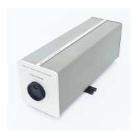
1-5. The HP 5517B/C/D Laser Head consists of a thermally-tuned laser tube, control circuits, a reference receiver,
and a high-voltage power supply. The laser head requires ±15 Volt supplies (refer to
Table 2-2
for power
requirement details). The HP 5517B/C/D produces a frequency stabilized laser beam and a balanced reference
output (see paragraph 1-6). Status LEDs, mounted on the HP 5517B/C/D's rear panel, provide information on power
supply inputs (±15 Volts) and fuses, laser and reference frequency outputs.
1-6. The HP 5517B/C/D laser beam consists of two linearly polarized and mutually perpendicular (orthogonal)
components separated in frequency by 1.9 - 2.4 MHz (HP 5517B), 2.4 - 3.0 MHz (HP 5517C), or 3.4 - 4.0 MHz (HP
5517D). The two components have light frequencies of and F
2
. The higher frequency component (F
2
) is oriented
perpendicular to the laser base, while the lower frequency component (F
1
) is parallel to the laser base. An optical
receiver inside the HP 5517B/C/D detects the 2.1 MHz (HP 5517B), 2.8 MHz (HP 5517C), or 3.7 MHz (HP 5517D)
frequency difference and places it at the rear panel connector as a balanced output (called the REFerence
Frequency). The reference output is one signal used by the external electronics to measure distance traveled.
NOTE
For making a measurement:
the HP 5517C Laser Head cannot be used with the HP 5527A or the HP
5501A Laser Transducer System electronics. It must be used with the HP
5527B laser system electronics, and
the HP 5517D cannot be used with the HP 5527A/B and HP 5501A. However,
for the procedures in this manual, any combination of Laser Head and laser
system electronics is allowed.
1-7. Except as described in
Table 1-1,
the HP 5517B/C/D Laser Heads are physically identical. The primary
difference between the Laser Heads is the difference between their laser beam frequencies. A larger frequency
difference allows measurements involving motion to be made at higher velocities (slew rates). (Velocity is an HP
5527A/B system Measurement Capability specification.)
Table 1-1. 5517B/C/D Laser Head Comparison
HP 5517B Freq: 1.9
MHz - 2.4 MHz
HP 5517C Freq: 2.4
MHz - 3.0 MHz
HP 5517D Freq: 3.4
MHz - 4.0 MHz
 Loading...

