Agilent 5890 3 Installation Procedure
3 Installation Procedure
3.1 GC Chromatograph setup
Installing the interface card in the GC unit
Note: Not necessary if the board is already installed
Unscrew and remove the right-hand panel of the chromatograph
Remove the original INET card
Set up the interface card - all switches on the DIP to the ON position
(closer to the outer edge of the card)
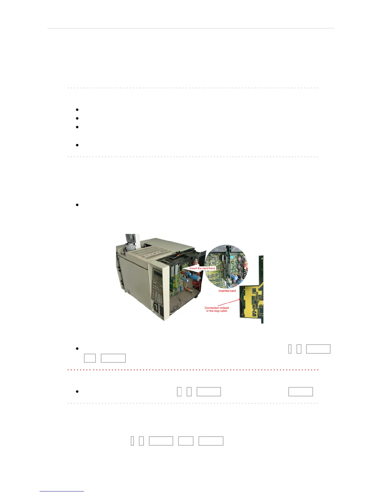
Insert the interface card
Note: On newer interface cards provided by DataApex company is the INET
loop connector disabled and the connection is provided by wires attached
to the back side of the card. If you want to use the loop cable for any
reason, cut off the wires on the back side of the card (Fig 2 on pg 3.).
Install the serial connector at the back of the GC (Models of the first series
5890A do not have a hole for this connector - then it is possible to put the
Cannon 25 connectors on the bottom of the GC)
Fig 2: Installation of the INET card
Switch the GC over to the Global Mode - press successively: . - 3 - ENTER -
ON - CLEAR.
Caution: Digital data acquisition works only in GLOBAL mode.
Test the INET loop function . - 7 - ENTER - and after the test - CLEAR.
Note: GC would not send „Ready“signal in local mode.
Analog acquisition alternative
When using A/D converter the GC has to be in Local Mode - press
successively: . - 3 - ENTER - OFF - CLEAR.
- 3 -