140 Diagrams
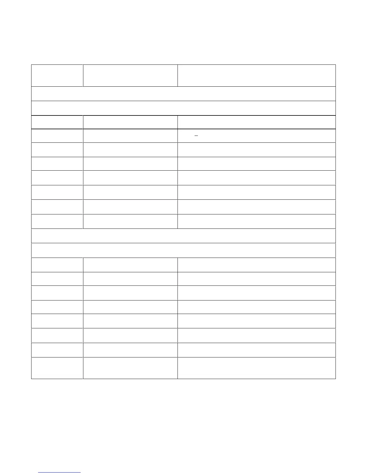
Table 6-3. Test Points
.TEST POINT
NUMBER
SIGNAL MEASUREMENT AND CONDITIONS
A2 GPIB BOARD (FIGURE 6-3)
Connect meter or scope common to test point ① when taking measurements at test points ② through ⑧ .
①
J106-4
Primary/chassis ground
②
U101-1
+ 5 V primary bias + 5V + 0.2V
③
U101-6
PCLR Goes high for approximately 40 ms at power on, then goes
low.
④
U101-8
PCLR* Held low for approximately 40 ms at power on, then goes high.
⑤
U110-3
STX Primary transmit to secondary serial data line. Toggles
between 0 and 5V.
⑥
U111-6
SRX Primary receive from secondary serial data line. Toggles
between 0 and 5V.
⑦
U119-4
FPRX Primary receive from front panel serial data line. Toggles
between 0 and 5V.
⑧
U119-18
FPTX Primary transmit to front panel serial data line. Toggles
between 0 and 5V.
A2 ISOLATOR BOARD (FIGURE 6-8)
Connect meter or scope common to test point ① when taking measurements at test points ② through ⑧ .
①
-C803
Primary/chassis ground
②
+U805-3
+ 5 V primary bias
+ 5V ± 0.2V
③
J800-2
SPCLR* (also called RESET*) Goes high for approximately 40 ms at power on, then goes
low.
④
J801-2
PCLR* Held low for approximately 40 ms at power on, then goes high.
⑤
J801-4
TxD Primary transmit to secondary serial data line. Toggles
between 0 and 5V.
⑥
J801-3
RxD Primary receive from secondary serial data line. Toggles
between 0 and 5V.
⑦
J800-4
Rx Primary receive from front panel serial data line. Toggles
between 0 and .5V.
⑧
J800-3
BSTx Primary transmit to front panel serial data line. Toggles
between 0 and 5 V.
 Loading...


