Diagrams 141
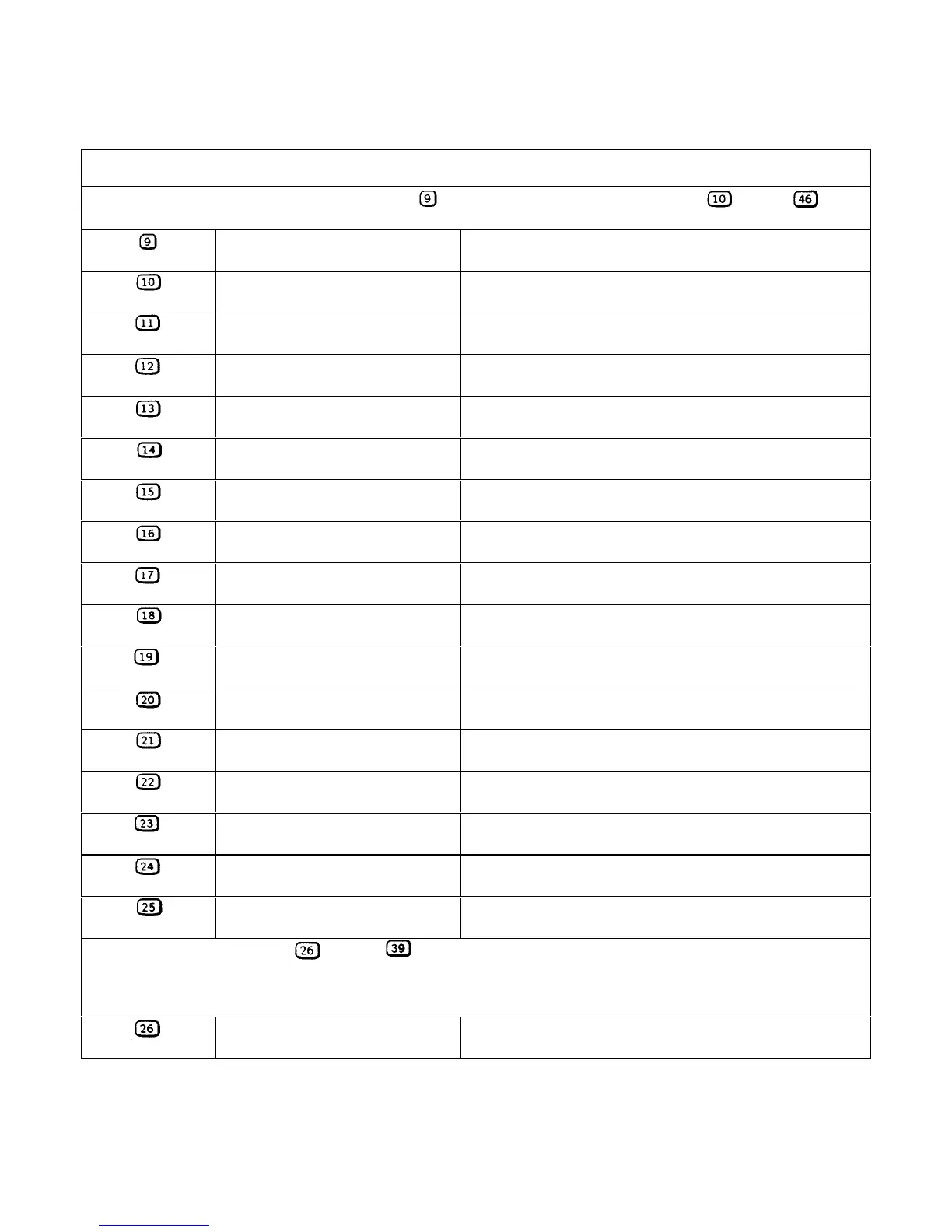
Table 6-3. Test Points (continued)
Al MAIN BOARD (FIGURE 6-5, Sheets 1-4)
Connect meter or scope common to test point when taking measurements at test points through .
-C770
Secondary common (Sheet 1)
R605
+ 5V Secondary bias (Sheet 1)
+ 5V ± 0.2V
+C604
+ 15V Secondary bias (Sheet 1)
+ 15V ± 0.6V
Q770 HS
+ 24V (Sheet 1) + 21V to + 27V (1V p-p ripple)
R607
- 15V Secondary bias (Sheet 1)
- 15V± 1V
U602-2
- 25V (Sheet 1) - 22V to - 28V (300mV p-p ripple)
U603-3
Fan speed control (Sheet 1) + 5 V with no load connected and an ambient temperature of
23°C
D606 anode
Fan speed control (Sheet 1) + 4 V with no load connected and an ambient temperature of
23°C
U720-6
SPCLR (Sheet 2) Goes high for approximately 40 ms at power on, and then goes
low
U608-3
Shutdown circuit (Sheet 2) + 8.1V
U721-16
Shutdown circuit (Sheet 2) 0.7V
D674 cath
+ 15 V GATED (Sheet 2) + 14.5V
D676 anode
- 15 V GATED (Sheet 2) - 14.5V
U505-6
CV/CC DACs ref (Sheet 3)
+ 10V ± 0.05V
U506-7
Readback DAC ref (Sheet 3)
- 11.58V ± 0.1V
U510-6
CCPROG (Sheet 2,3) - 8.5V approximately with FS current programmed
U508-6
CVPROG (Sheet 2,3) - 9.5V approximately with FS voltage programmed
The measurements at test points through were taken with full scale voltage and full scale current programmed
The measurements were made first in the CV mode with no load and then in the CC mode with the load set for full scale
output voltage and current. If the CC annunciator is not on, set the current to a slightly lower value until it comes on.
U605-7
CC control (Sheet 2) 2.2V in CV mode - .25V (6651-54), - 33V (6655) in CC mode
 Loading...


