Schematic Notes For Figure 6-1
1. Fuse F1 is 8A for 100/120 Vac input or 4A for 220/240 Vac input.
2. Before connecting the supply to the power source, check that the position of the line voltage selector card matches the
nominal line voltage source (100, 120, 220, or 240 Vac). See Section II in the Operating Manual (Agilent Part No. 5957-6377) for
details.
3.
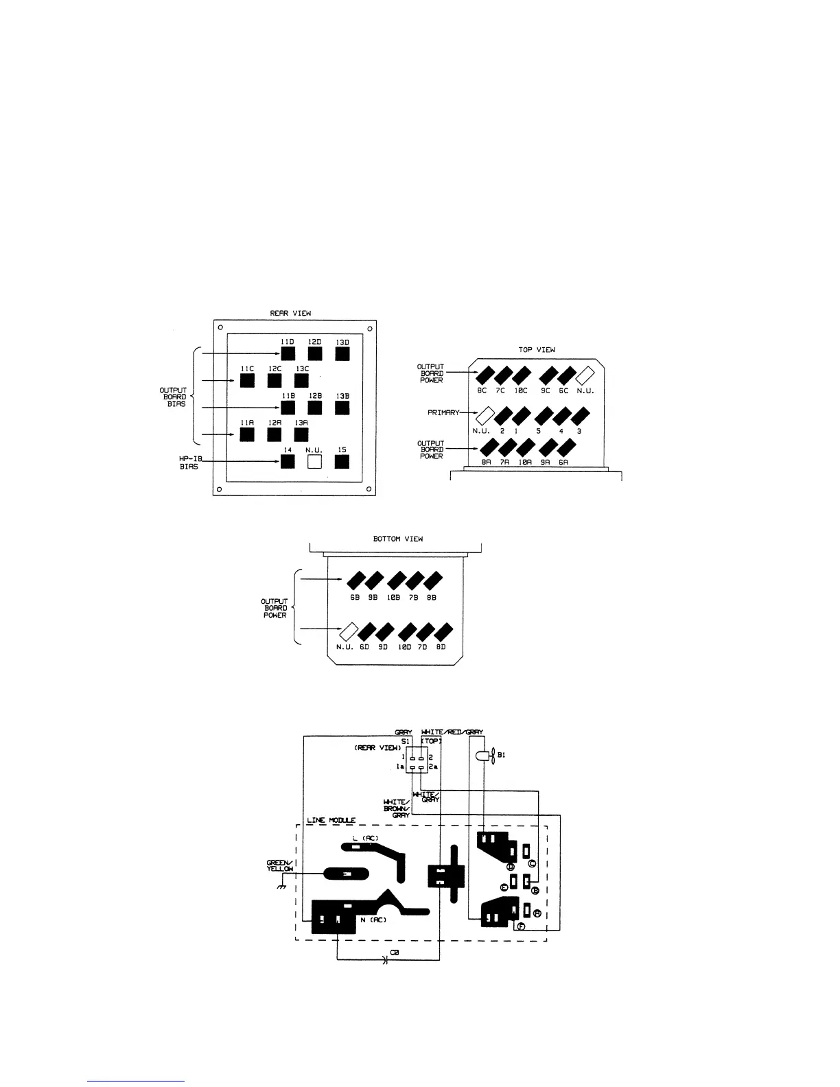
4. The line module connections are shown below.
The reference designators (W1, W2, etc.) for the cable assemblies are for schematic reference only. Use the Agilent part
numbers to physically identify cables in the supply. Each cable is marked with the appropriate Agilent Part No. The
illustration below shows the transformer T1 terminal designations. The illustrations on pages 6-2 and 6-3 show the
transformer T1 connections and cable part numbers for each model.
6-4