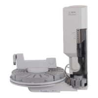
Agilent 708-DS Dissolution Apparatus
Training Manual
Revision A September 2010
P/N: xx-xxxx
2.1.4. Instrument Power Up
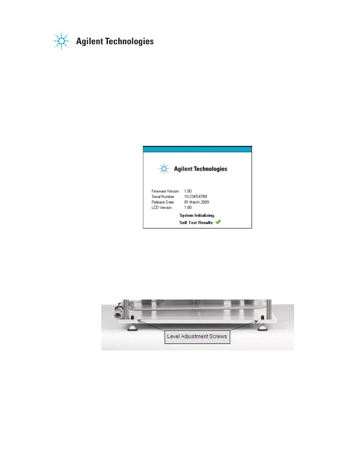
Once the cables have been connected, the apparatus is powered ON
using the switch on the left side of the drive unit. Upon initialization, the
instrument undergoes a brief “Self-Test” to ensure proper operation. At
this time, the serial number, firmware version, firmware release date, and
LCD version are displayed. A green check mark indicates the test was
successful. A red “X” appears if any of the system components fail the
test along with the status of each component. The error screen will
appear until the condition is resolved and the internal routine completes
successfully.
Figure 2-2. Built-in Self Test Screen
2.1.5. Leveling the Apparatus
Adjustment of the vessel plate level is performed by using the 90° Allen
Key and the 17-mm open-end wrench supplied with the apparatus. The
first step is to remove the black caps that cover the level adjustment
screws on the front and rear of the base plate (see Figure 2-3).
Figure 2-3. Level Adjustment Screws
Raise the stability feet located toward the back on either side of the base
plate so they are not touching the laboratory bench.
NOTE: It may be necessary to use the open-end wrench to loosen the nut(s) beneath the
base plate to allow for adjustment of the leveling screws.

 Loading...