70 Advanced Operation
5 Configuration
APG Remote - Suggested drive circuits
A signal on the APG bus may be driven by another APG
device or by one of the following circuits:
• A relay, with one side connected to ground, when closed
will set a logic- low state.
• An NPN transistor, with the emitter connected to ground
and the collector connected to the signal line will set a
logic- low state if proper base current is supplied.
• An open- collector logic gate will perform this same
function.
• A low- side drive IC will also work, but Darlington- type
drivers should be avoided as they will not meet the
low- side voltage requirement of less than 0.4 V.
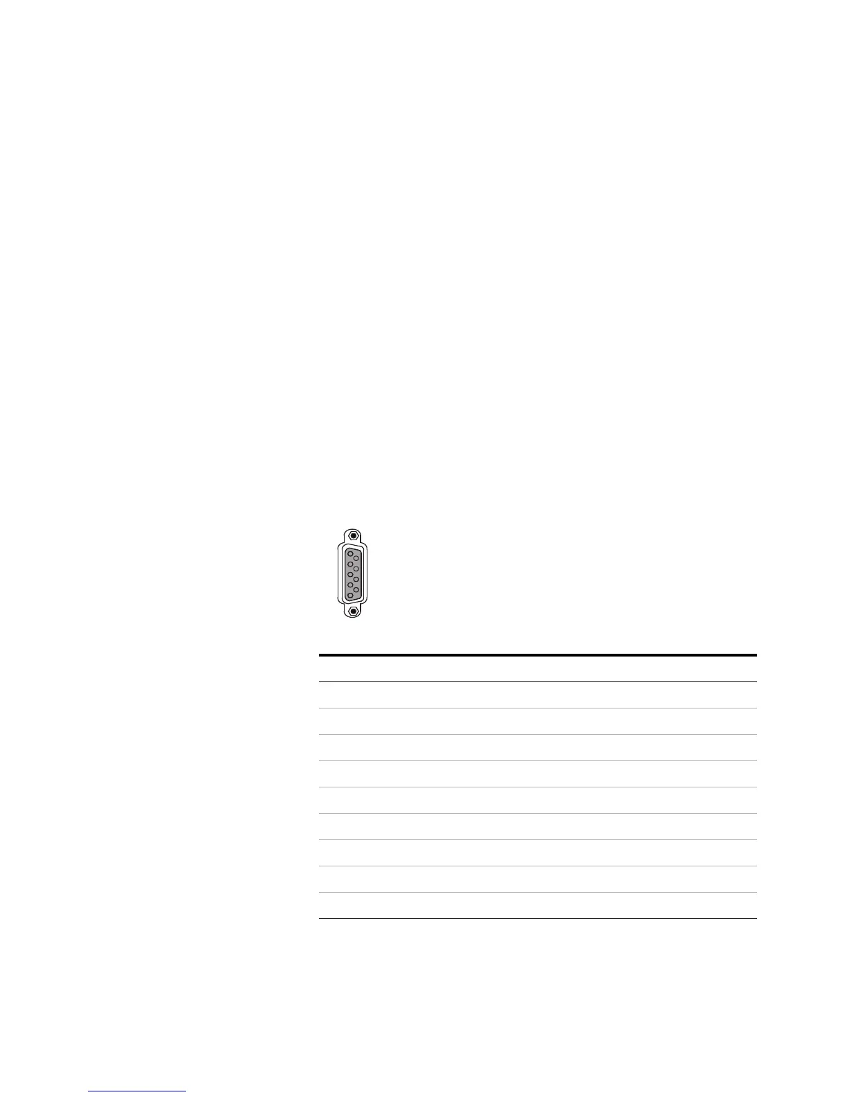
APG Remote connector
The signals for each pin on the connector are shown below.
APG Remote signal descriptions
Ready (High True): If the ready line is high (> 2.2 VDC)
Pin Function Logic
1 Digital ground
2Not used
3 Start LOW true (input)
4 Start relay
5 Start relay
6Not used
7 Ready HIGH true (output)
8Not used
9Not used
1
6
9
5

 Loading...


