40 7820A GC Installation Manual
7820A GC Installation Guide
Cable Diagrams
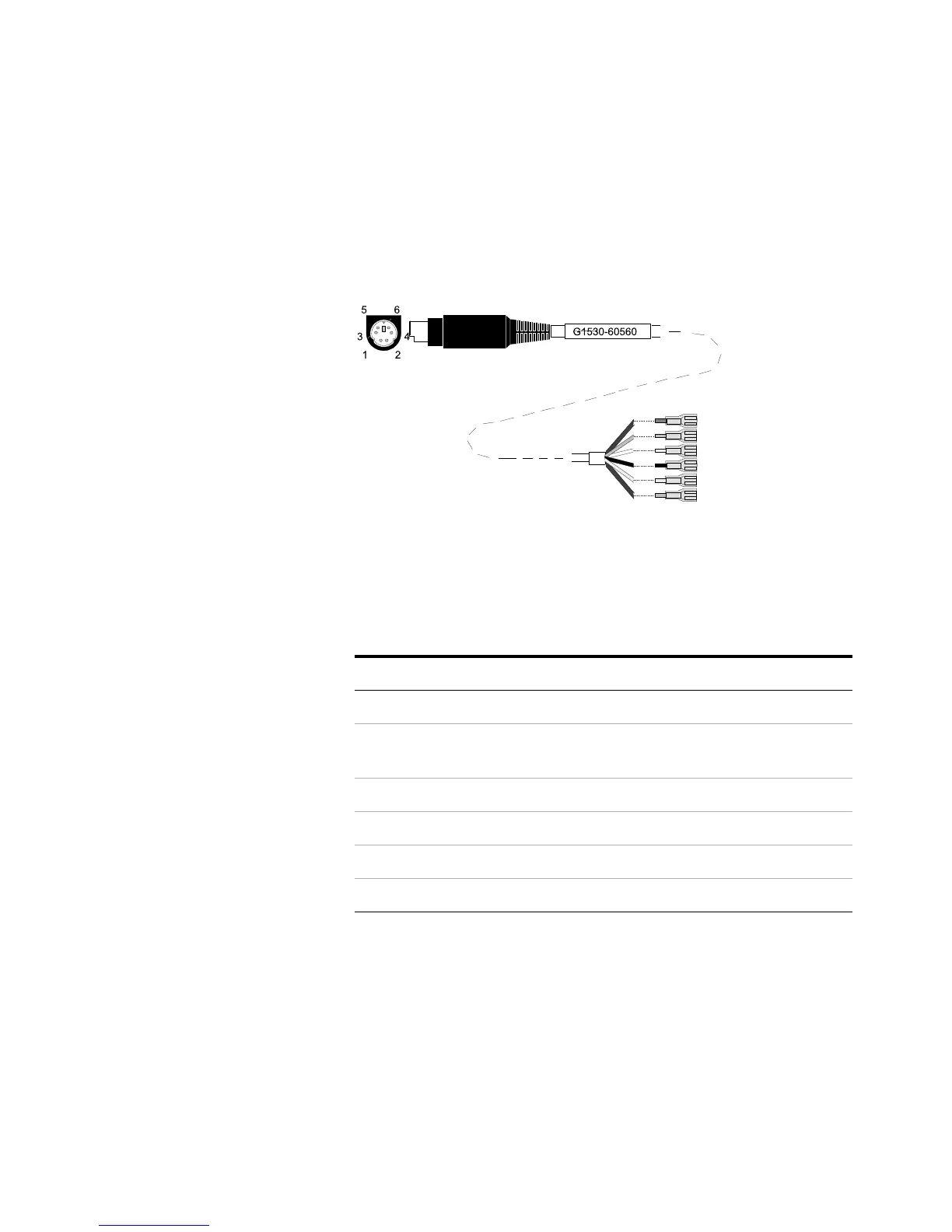
Analog cable, general use
The pin assignments for the general use analog out cable
are listed in Table 3.
Table 3 Analog cable, general use, output connections
Connector 1 Connector 2, wire color Signal
1 Brown or violet Not used
2 White 0 to 1 V, 0 to 10
V (–)
3 Red Not used
4 Black 1 V (+)
6 Blue 10 V (+)
Shell Orange Ground
Connector 1
Connector 2

 Loading...


