Chapter 7 161
Troubleshooting the Processor, Power Supply, and Display
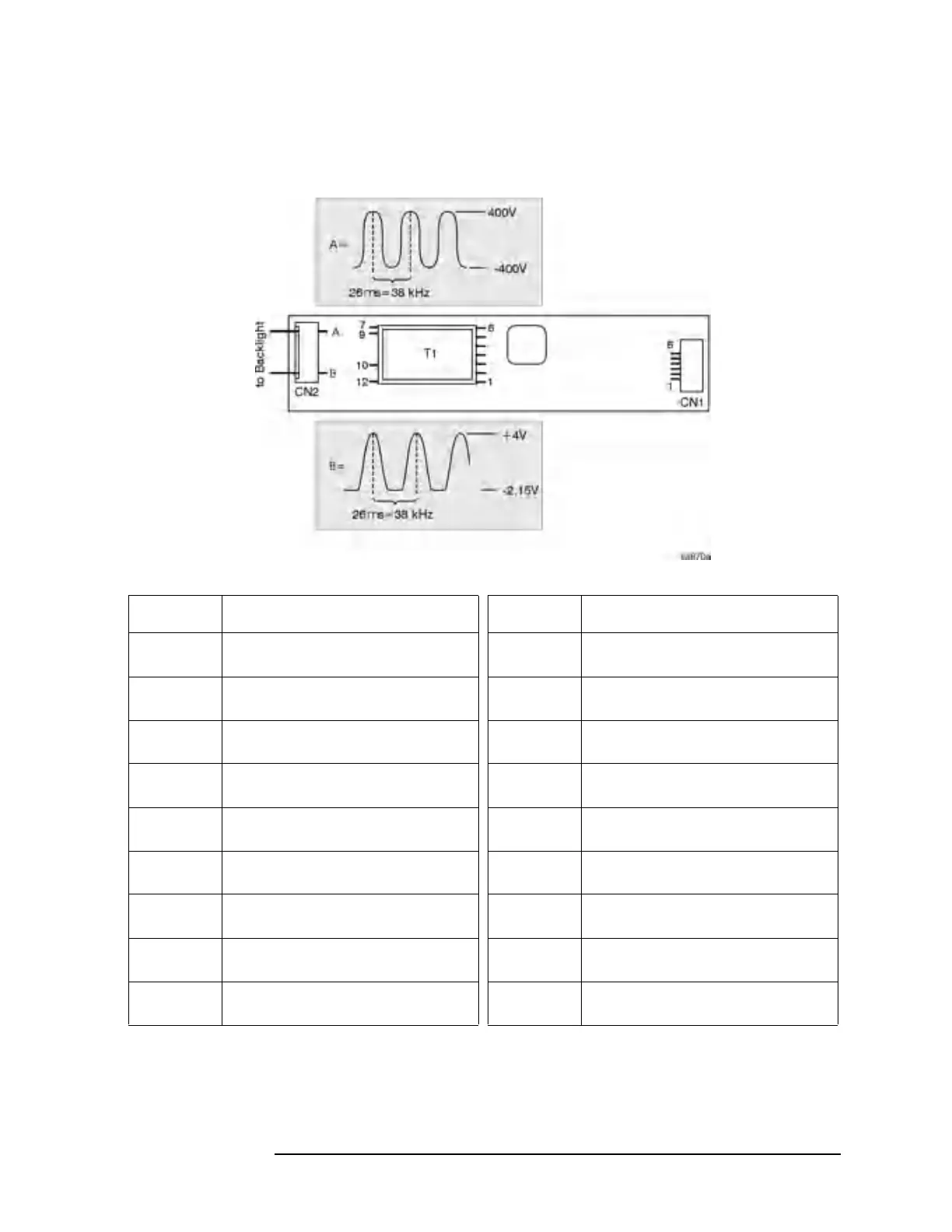
Isolating a Display Problem
Figure 7-2 Verifying the Inverter Boards
Test Point Signal or Voltage Test Point Signal or Voltage
CN1 pin 1 +4.9 Vdc T1 pin 4
(input)
+3.3 Vdc
CN1 pin 2 +4.9 Vdc T1 pin 5
(input)
+33.4 mV
CN1 pin 3 26 mV T1 pin 6
(input)
−.30 Vdc
CN1 pin 4 +33 mV T1 pin 7
(output)
60 V p-p sinewave @ 38 kHz
CN1 pin 5 +33 mV T1 pin 9
(output)
77 V p-p sinewave @ 38 kHz
CN1 pin 6 +33 mV T1 pin 10
(output)
450 V p-p sinewave @ 38 kHz
T1 pin 1
(input)
−.30 Vdc T1 pin 12
(output)
45 V p-p sinewave @ 38 kHz
T1 pin 2
(input)
+3.3 Vdc CN2 A −400 V to +400 V sinewave @ 38 kHz
(see figure)
T1 pin 3
(input)
+3.3 Vdc CN2 B −2.15 V to +4 V sinewave @ 38 kHz
(see figure)
 Loading...


