332 Chapter 11
Assembly Replacement Procedures
RF Section E4440A, E4443A, E4445A
Option 123 Switches
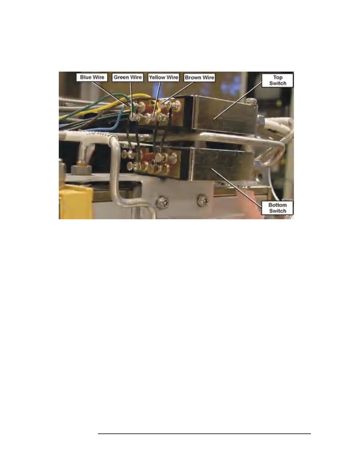
Figure 11-19 Option 123 Switch Wiring
Top Switch Removal
1. Drop the front frame. See page 314 for instructions.
2. Note the locations of the soldered wires on the switch terminals,
particularity the black wires. Figure 11-19 shows most wire
locations.
3. Unsolder and remove the wires from all top switch solder-on
terminals. When removing the black wires, avoid damaging the
wires since there is little service length. The colored wires usually
have extra length and you may wish to just cut them off and re-strip
the ends.
4. Refer to Figure 11-17. Remove cables W84, W86, and W87 from the
top switch. Note that two of the cables have identification bands that
correspond to the connector designator 1, or 2, printed on the switch.
5. Remove the two switch mounting screws and remove the switch. Be
careful that the standoffs between the two switches are not lost.
 Loading...


