Chapter 3 79
Troubleshooting the RF Section (E4440A, E4443A, E4445A)
RF Section Description (E4440A, E4443A, E4445A)
signal should be 3 to 7 GHz at +12 to +17 dBm. Next verify the LO
outputs, all of which range from 3 to 7 GHz. To verify the High Band
output, set the PSA to a center frequency of 5 GHz and set the span to
0 Hz. The High Band LO Output should be 14.5 dBm ±3 dB. Verify the
Low Band LO output by setting the PSA to a frequency below 2.85 GHz
in zero span, and verify that the signal is 14.5 dBm ±1 dB. The signal at
the SAMPLER OUT should range from –8 dBm to –3 dBm and the
1
st
LO OUT should be around 15 dBm.
NOTE The DC voltages on the SLODA can be measured either at the
connectors to the SLODA, or at A13J12 using the E4440-60041 bias
board (included in Service Kit E4440-60090). Measuring at the SLODA
will help verify the condition of the A13-to-SLODA bias cable, W28.
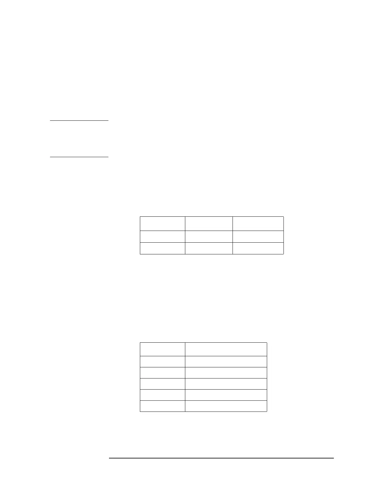
If either the Low Band or High Band outputs are bad, check that the
band switch is being driven properly. To set the PSA to Low Band, set
the Center Frequency below 2.85 GHz in Zero Span. Set the analyzer
above 3 GHz for High Band. A DVM with a fine probe can be used to
reach the connections at the SLODA. Connect the negative lead to A13
TP11, or to A13J12 pin 10 (SLODACOM) if the bias board is available.
Using a DVM, verify that the Gate Bias is close to the value printed on
the SLODA label. If probing on A13J12, measure at pin 9 (GATE BIAS
on the bias board.)
For the ALC, verify that the Level Adj pin reads between –0.5 V to –3 V.
INT Sense can be measured at A13J12 pin 8 (INT SENSE on the bias
board) as well as at the SLODA. With the E4440 in Zero Span, set the
Center Frequency to the frequencies listed and measure the INT Sense
voltages. They should be close to the values printed on the SLODA label
for each band.
EXT Sense is used when Option AYZ External Mixing, or Option 123,
Unpreselected Path is installed. EXT Sense line goes to the Front End
Driver assembly and is MUX’d into the SLODA LO levelling loop.
SLODA Pin High Band Low Band
SW A −1 V 1 V
SW B 1 V −1 V
Band Frequency Range
B0 30 Hz to 3 GHz
B1 2.85 GHz to 6.6 GHz
B2 6.2 GHz to 13.2 GHz
B3 12.8 GHz to 19.2 GHz
B4 18.7 GHz to 26.5 GHz
 Loading...


