Service Guide E8364-90038 7-13
PNA Series Microwave Network Analyzers Repair and Replacement Procedures
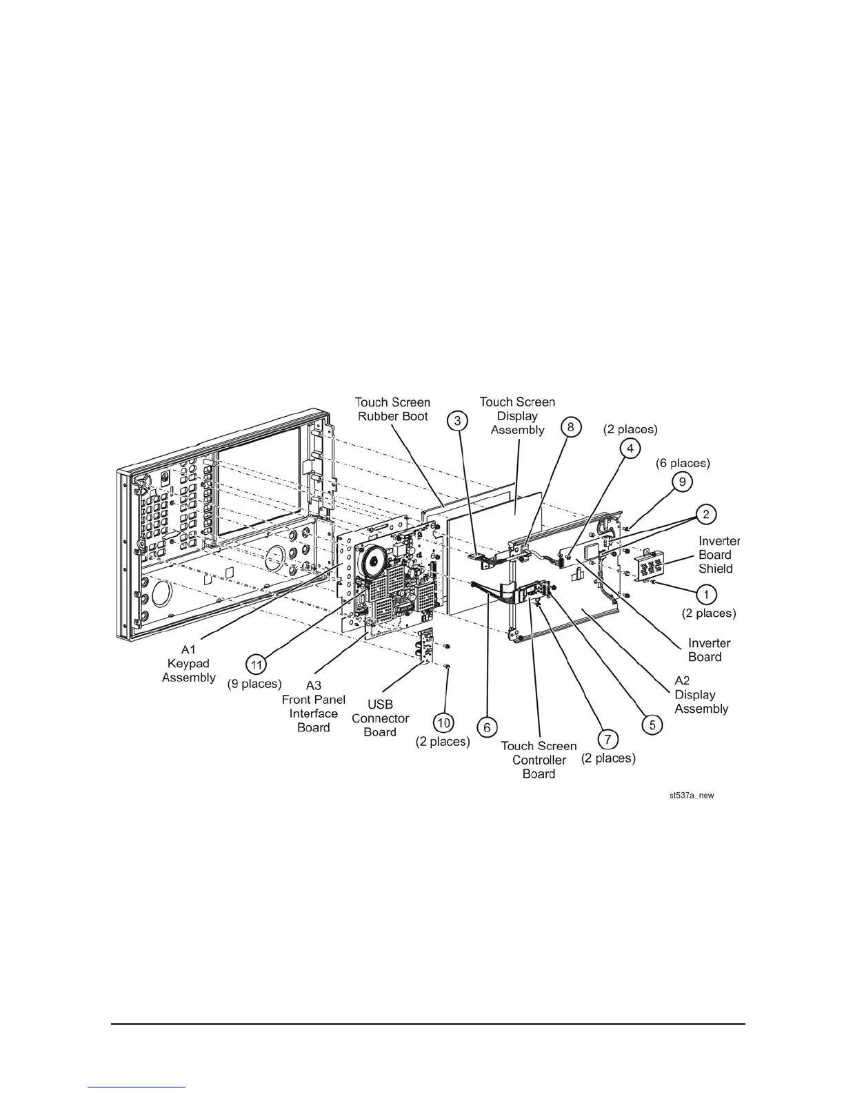
E8362C, E8363C, E8364C Removing and Replacing Front Panel Subassemblies
Replacing the A2 Display Assembly
1. Remove the inverter board. Refer to the procedure on page 7-12. Remove the inverter cable from the
cable clamp (item
⑧
).
1. Remove the touch screen controller board. Refer to above procedure.
2. Remove the six retaining screws (item
⑨
) from the A2 display assembly.
3. Remove the A2 display assembly from the front panel assembly.
4. Install the new A2 display assembly by reversing the removal instructions.
5. Perform the post-repair adjustments, verifications, and performance tests that pertain to this
replacement procedure. Refer to Table 7-2 on page 7-82.
Figure 7-4 Front Panel Subassemblies Removal
 Loading...


