Specifications and Characteristics 6
U3402A User’s and Service Guide 105
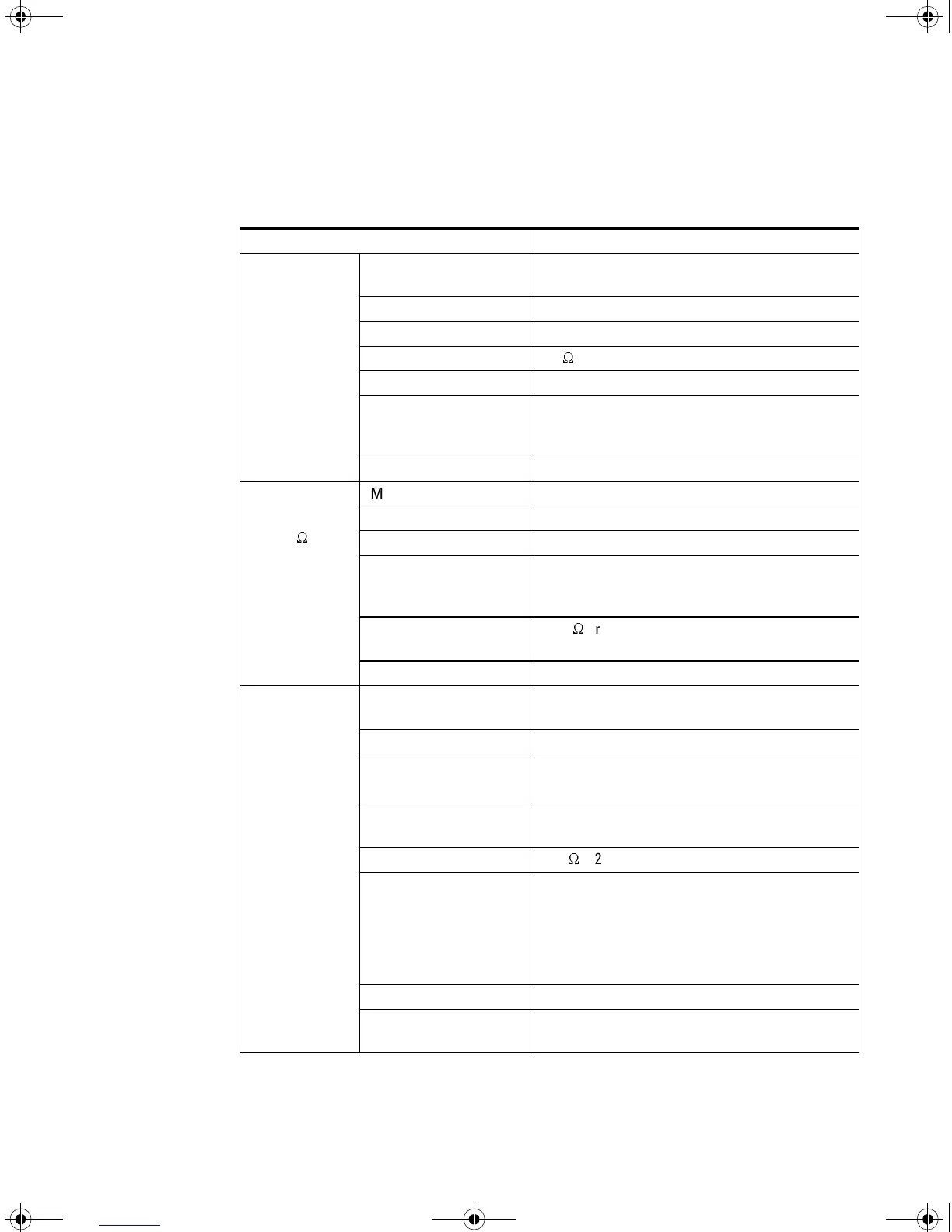
Measurement Specification
Diode/
Continuity
Measurement method
0.83 mA±0.2% constant current source,
open-circuit voltage limited to <5 V
Test current Approximately 0.5 mADC
Open-circuit voltage Limited to < +5 VDC
Continuity threshold 10
W
fixed
Continuity level Approximately < +50 mVDC
Audible tone
Continuous beep for continuity and single tone for
normal forward-biased diode or semiconductor
junction
Input protection 500 V RMS on all ranges
Resistance/
Continuity
(2-wire
W
)
Measurement method 2-wire Ohms
Test current Approximately 0.5 mADC
Open-circuit voltage Limited to < +5 VDC
Audible tone
Continuous beep for continuity and single tone for
normal forward-biased diode or semiconductor
junction
Zeroing error
0.05
W
or less (excluding test lead resistances) in
each range when Rel operation is used
Input protection 500 V RMS on all ranges
Frequency
Measurement method
Reciprocal counting technique. AC coupled input
using AC voltage function.
Crest factor Maximum 3:0 at full scale
Signal level
10% of range to full scale input on all ranges
Auto or manual range selection
Gate time
0.1 second or 1 period of the input signal,
whichever is longer
Input impedance 1 M
W
± 2% in parallel with <120 pF of all ranges
Maximum input voltage
750 V RMS /1100 V PEAK
2x10
7
V-Hz product on any range, normal mode
input
1x10
6
V-Hz product on any range, common mode
input
Input protection 750 V RMS on all ranges
Response time
Approximately 1.5 seconds when the displayed
reading reaches 99.9% of frequency value.
Table 6-13 Supplemental measurement specifications
U3402-90001.book Page 105 Friday, July 24, 2009 4:04 PM
Downloaded from Elcodis.com electronic components distributor
 Loading...


