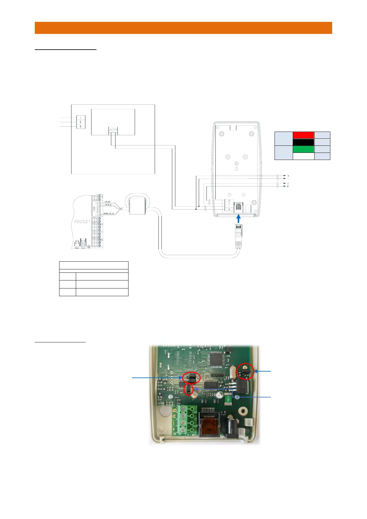
EasyManua.ls Logo

Aidcall Touchsafe Pro - System Log Viewing; Zoned Pager Setup; Common Pager Setup

Aidcall Touchsafe Pro
33 pages
Print Icon
To Next Page IconTo Next Page
To Previous Page IconTo Previous Page
Loading...
Doc No. FM5600 issue E Page 12
10. INTERFACE INSTALLATION
CONNECTION DETAILS
Loop the Patch Lead through the ferrite sleeve provided and connect the 3 wires to the Pager terminal in
the Touchsafe Pro Nursecall panel using the colour code shown below.
Plug the Patch Lead into the RJ45 socket on the bottom of the Interface.
Connect the Battery Backed 12V PSU output to the Interface +/- supply terminals.
Connect the 2 pair power and RS485 data bus cable for the Master and Slave Bases to the interface using
the colour code shown in the table above.
JUMPER SETTINGS
Check the Jumpers are set
on the PCB inside as shown…
IMPORTANT
Loop the Patch Lead once through the Ferrite
Sleeve provided with the Nursecall Panel
Interface
Battery Backed
12V/1A PSU
2m Patch Lead
240VAC
Mains
Supply
2 Pair Bus to
Master/Slave
Bases
Battery Back-up
Jumper not fitted
Pager Output Terminals
TX
Green
RX
Orange
0V
White/Blue
Plug Patch Lead
into Interface
Remove both Data Jumpers
and park on RHS pins as
shown here
RS485 End of Line
(EOL) Jumper only
fitted on the first
and last units on the
RS485 Bus Cable.
Power
Red
+
Black
-
Data
Green
A
White
B

Other manuals for Aidcall Touchsafe Pro