The Master Base is connected on a 2 pair bus from the Interface. Depending on the size of the site, up to 7
Slave Bases can also be connected on the same bus to achieve extended radio coverage.
The maximum cable length for the power supply pair is 100 metres, for greater distances an additional PSU
will be required at a remote point in the building. The maximum cable length for the RS485 bus is 600
metres – this must be one continuous “daisy-chain” connection.
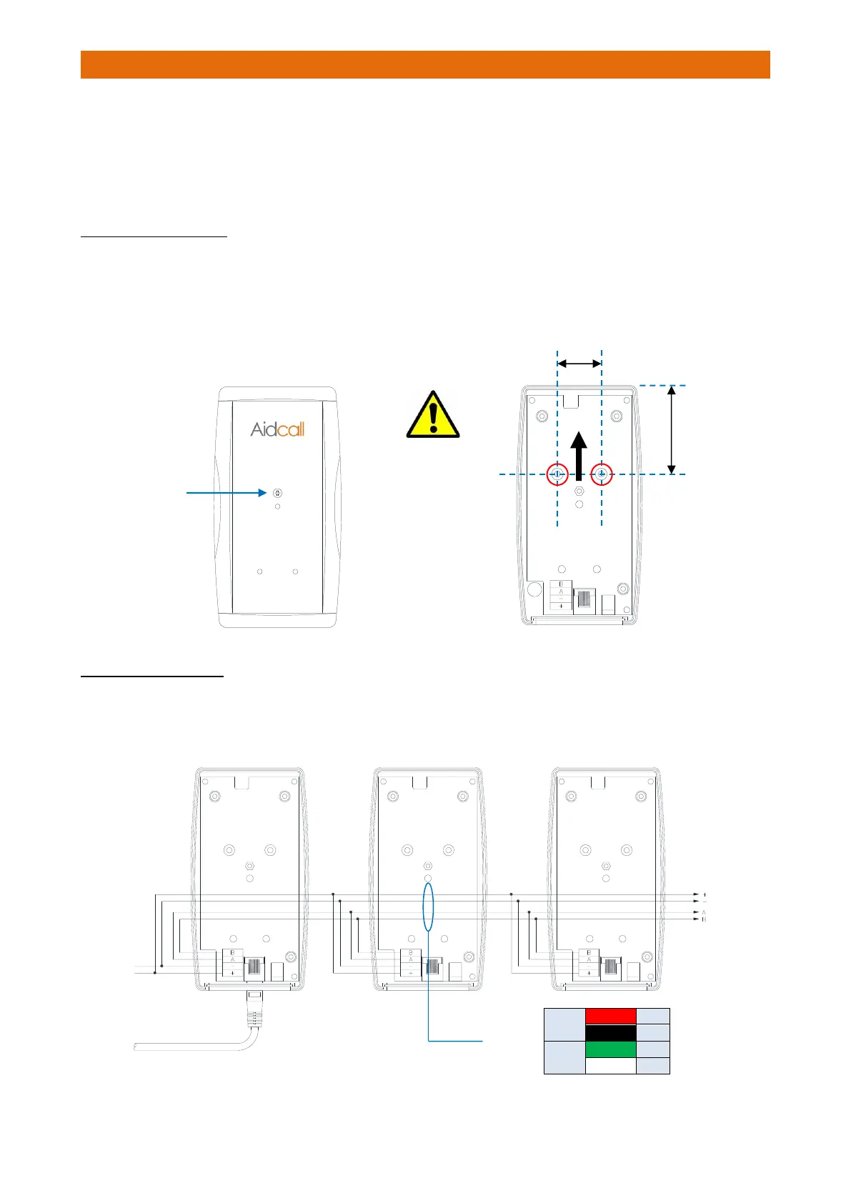
MASTER/SLAVE FIXING
Undo the single screw fixing in the centre and remove the lid.
Choose the best position as close as possible to the location recommended by the RF site survey.
Fix the unit to the wall using the screws provided through the 2 fixing holes “A” shown below.
IMPORTANT: to ensure maximum radio coverage always fix the Master/Slave Bases vertically with the
connectors at the bottom as shown below;
CONNECTION DETAILS
The Master and Slave Bases should be wired using LSF 2 Pair 22AWG individually screened data cable.
Use Belden Type 8723 or equivalent, available from Aidcall; Part No. YW1715 (100m reel).