The Interface requires power from the 12V/1A battery backed PSU and RS232 data from the Pager Port on
any Touchsafe Pro Nursecall panel.
The Interface unit is normally located in close proximity to the Nursecall panel and is connected using the 2
metre Patch Lead provided. Note: this cable can be extended up to 20 metres maximum if necessary.
The Interface converts RS232 data from the panel to RS485 for connection to the Master and Slave Bases.
Note: the maximum length for the RS485 bus cable is 600 metres.
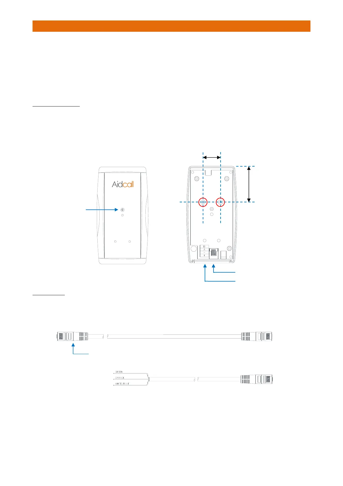
INTERFACE FIXING
Undo the single screw fixing in the centre and remove the Interface lid.
Choose a location to fix the Interface within 2 metres cable run of a Nursecall panel.
Fix the Interface to the wall using the screws provided through the 2 fixing holes “A” shown below.
PATCH LEAD
Cut an RJ45 plug off one end of the 2 metre Patch Lead (Aidcall Part No. W00402).
Strip-back the cable and identify the green, orange and white/blue wires.