- 26 -
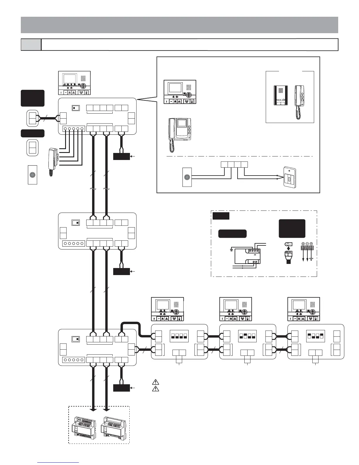
Standard system for residence (station-to-station wiring)4-2
GT-VBC GT-BC
GT-1C-L
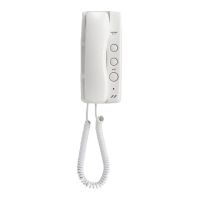
GT-1C
GT-1M-L
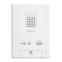
GT-1A GT-1D
GT-2C-L
GT-2C
GT-2C-L
GT-2C
GT-2C-L
GT-2C
GT-2H-L
GT-2H
#1 #2 #3 GT-2H-L
GT-2H
PS24
AC
PS24
AC
PS24
AC
JK-DA
JK-DV
JK-DVF
GT-D
PS24
+
-
100V - 240V -
50/60 Hz
24V DC
2 A
PS-2420
PS-2420S
PS-2420UL
PS-2420DIN
CCEKKE
IN
OUT
SW1
B
A
A1
A2
H1
H2
B1
B2
R1
R2
B1
B2
R1
R2
+
-
+
-
CN4
A1
A2
1
2
ON
12
3
4
SW2
IN
OUT
H1
H2
+
-
H1
H2
+
-
ON
12
3
4
SW2
IN
OUT
H1
H2
+
-
H1
H2
+
-
IN
OUT
A1
A2
H1
H2
B1
B2
R1
R2
B1
B2
R1
R2
+
-
+
-
CN4
SW1
B
A
IN
OUT
A1
A2
H1
H2
B1
B2
R1
R2
B1 B2 R1 R2
+
-
+
-
CN4
SW1
B
A
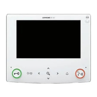
GT-HS
GT-2H-L
GT-2H
ON
12
3
4
SW2
IN
OUT
H1
H2
+
-
H1
H2
+
-
1P
NP
1P
NP
1P
NP
1P
NP
1P
NP
1P
NP
1P
NP
1P
NP
1P
NP
1P
NP
230 V AC
N
L
24 V DC2A
IN 230V~ 50/60Hz
NL
2A
-
+
-
+
SW
SW
SW
SW
SW
SW
Terminal setting:
For the terminating residential station,
turn SW1 to the [A] side.
Terminal setting:
For the terminating residential station,
turn SW1 to the [A] side.
Terminal setting:
For the terminating
residential station, turn
SW1 to the [A] side.
Terminal setting:
For the
terminating sub
master station,
turn 4 on SW2
to ON.
Emergency alarm switch
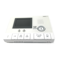
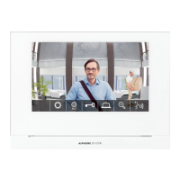
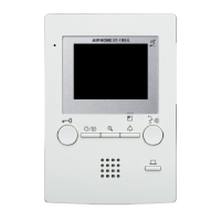
Residential station
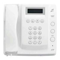
Audio only
Doorbell
Residential station
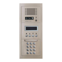
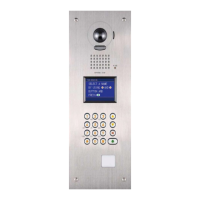
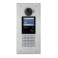
Door
station
Doorbell
Option contact output (4-5) Option contact output (4-5) Option contact output (4-5)
1. For other residential station connections, refer to [4-5 Option connector].
2. After connecting a GT-2C(-L) and a door station (or doorbell), be sure to turn the
power supply off and on again.