Do you have a question about the AIREDALE R410A and is the answer not in the manual?
Details of warranty coverage for Airedale products, including parts and labour.
Information about available spare parts lists for various years.
Information on Airedale's Refrigeration and Air Conditioning Training courses.
Contact information for various Airedale customer support departments.
Disclaimer regarding the accuracy and use of information in the manual.
Recommendation for using PPE during installation and maintenance.
Warnings and guidelines for handling R410A refrigerant.
Advice on safe manual handling and environmental practices.
Explanation of the unit's model naming convention and its components.
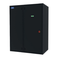
Overview of the SmartCool range and its applications.
Certification of compliance with relevant EC Directives.
Details of the chilled water single circuit system.
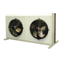
Details of air-cooled direct expansion systems.
Requirements for providing precision air conditioning in specific environments.
Details on the unit's cabinet construction, materials, and finish.
Overview of refrigeration and airflow system components.
Location of incoming mechanical service connections.
Table detailing standard and optional refrigeration features.
Details on the evaporator coil construction and testing.
Information on compressor mounting, tandem configurations, and valves.
Detailed explanation of EEV operation and benefits.
Illustration of EEV efficiency benefits using a Mollier diagram.
Explanation of the suction throttle valve for capacity control.
Graph illustrating capacity and EER based on suction throttle valve position.
Overview of chilled water, airflow, and humidification components.
Table detailing standard and optional chilled water features.
Details on the construction and testing of the chilled water coil.
Function of the 3-port and 2-port regulating valves.
Details on threaded pipe connection options.
Table detailing standard and optional airflow features.
Details on fan and motor assembly features.
Explanation of EC fan motor technology and benefits.
Details on G4 and high-efficiency filter options.
Function of the airflow switch for fan failure detection.
Overview of electrical components and the control panel.
Details on the control panel contents and wiring standards.
Information on sub-fusing and electric heating elements.
Features of dual power supply, Ultracap UPS, Energy Manager, and Phase Rotation Protection.
How steam is produced and modulated in the humidifier.
How system lifetime is optimized via a water conductivity sensor.
Description of de-humidification features, including rapid mode.
Information on water conductivity and matching cylinder types.
PCOS Microprocessor and PGD1 Display features.
Constant Air Volume, Pressure, Temperature, and Humidity Control.
NTC probes, filter switch, BMS, and detection systems.
Features and usability of the display keypad.
Password, Remote On/Off, Fire Shut Down, Compressor controls.
Compressor/fan run logs, filter alarms.
Head pressure and fan speed control.
Network, Duty/Standby, Smart Key, Audible Alarm, Low Ambient Kit.
Water, Fire, Refrigerant Leak, and Smoke Detectors.
Temperature control, alarm logging, and supply air temp control.
Duty rotation and BMS interface card compatibility.
Method for controlling air pressure using variable speed fans.
Method for adjusting fan speed to deliver specific air volume.
Table listing standard and optional general features.
Details on floor stand and ceiling duct extension options.
Details on unit packaging for transit protection.
Details on hot and cold water condensate pump types and their performance.
Incorporation of a float switch for drain tray monitoring.
Methods for measuring and quoting sound data.
Notes on sound data basis and potential increases.
Diagrams showing the physical dimensions of the units.
Tables specifying minimum clearances for floorstand and ceiling.
Details on unit packaging for transportation.
Guide for selecting appropriate refrigerant pipe sizes.
Requirements for oil trap placement and pipe support distances.
Guidelines for passing refrigerant lines through walls.
Considerations for liquid line configuration and pipe insulation.
Design considerations for vertical refrigerant risers.
Guide for estimating refrigerant quantities for split systems.
Caution regarding sizing double riser systems.
Equation for calculating total system refrigerant charge.
Equation for calculating liquid line refrigerant charge.
Calculation of pressure loss and subcooling required to prevent flashing.
Guide for calculating additional oil required for the system.
Pipework schematic for the C000 system.
Diagrams showing pipework configurations for X1X1 models.
Diagrams showing pipework configurations for X200 models.
Diagrams showing pipework configurations for X100 models.
Details on incoming service connections for C000 units.
Details on incoming service connections for X200/X100 units.
Details on incoming service connections for X1X1 units.
Visual representation of incoming electrical services.
Equation to calculate design volumetric flow rate.
Equation to calculate indoor unit pressure drop.
Table of specific heat capacity for glycol mixtures.
Tables of density and pressure drop correction factors for glycol.
Table of performance data for X100/X200/X1X1 models.
Defines the operating limits for the units.
Table of performance data for X100/X200/X1X1 models.
Defines the operating limits for the units.
Table of sound data for SC09D models.
Table of sound data for SC15D and SC18D models.
Wiring schematics for X1X1 models with AC and EC condensers.
Wiring schematics for X1X1 models with three phase and SCAF condensers.
Wiring schematics for X1X1 models with SCAF condensers and control functions.
Wiring schematics for X100/X200 models with AC and EC condensers.
Wiring schematics for X100/X200 models with three phase condensers.
Wiring schematics for X100/X200 models with SCAF condensers and control functions.
Table of performance data for C000 models.
Table of sound data for C000 models.
Graph and table for pressure drop calculations.
Wiring schematics for C000 models.
Details of Airedale product warranty terms and conditions.
Steps for obtaining replacement parts under warranty.
Reasons for warranty refusal and returns analysis process.
| Brand | AIREDALE |
|---|---|
| Model | R410A |
| Category | Accessories |
| Language | English |