I
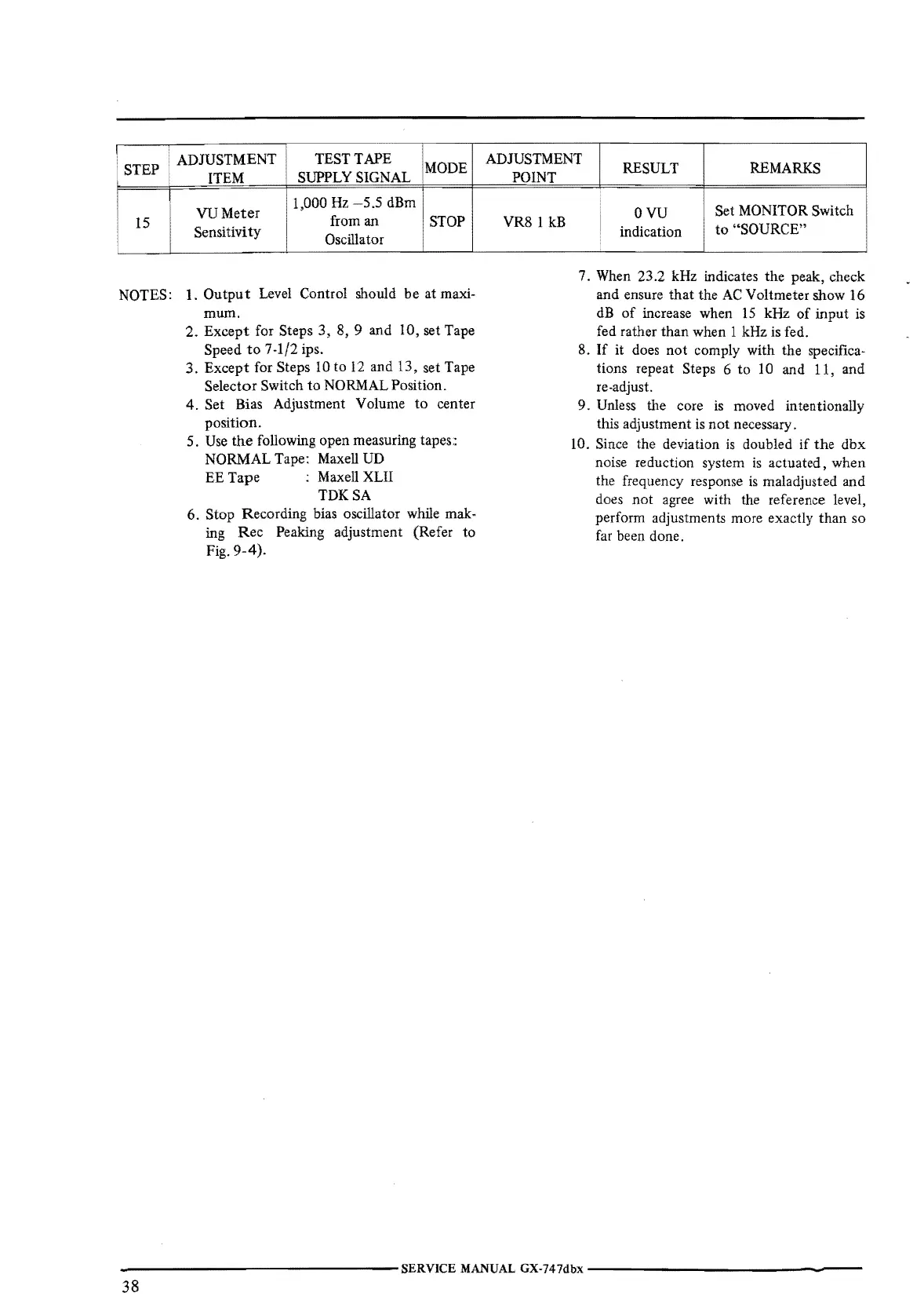
ADJUSTMENT
TEST TAPE
• STEP
MODE
ITEM
SUPPLY SIGNAL
VU
Meter
1,000
Hz
-5.5
dBm
15
from an
STOP
Sensitivity
Oscillator
NOTES:
1.
Output
Level Control should
be
at maxi-
mum.
2.
Except
for Steps
3,
8, 9
and
10, set Tape
Speed
to
7-1/2 ips.
3.
Except
for Steps
IO
to
12
and 13, set Tape
Selector Switch
to
NORMAL Position.
4. Set Bias Adjustment Volume
to
center
position.
5. Use
the
following open measuring tapes::
NORMAL Tape: Maxell UD
EE
Tape
: Maxell XLII
TDKSA
6.
Stop
Recording bias oscillator while mak-
ing
Rec
Peaking adjustment (Refer
to
Fig.
9-4).
ADJUSTMENT
RESULT REMARKS
POINT
VR8
1 kB
ovu
Set MONITOR Switch
indication
to
.. SOURCE"
7. When 23.2 kHz indicates
the
peak, check
and
ensure
that
the AC Voltmeter show 16
dB
of
increase when
15
kHz
of
input
is
fed rather
than
when 1 kHz is fed.
8.
If it does
not
comply with the specifica-
tions repeat Steps
6
to
10
and 11, and
re-adjust.
9. Unless the core
is
moved intentionally
this adjustment is
not
necessary.
10. Since the deviation
is
doubled
if
the
dbx
noise reduction system
is
actuated,
when
the frequency response
is
maladjusted and
does
not
agree with the reference level,
perform adjustments more exactly
than
so
far
been done.
----------------SERVICE
MANUAL
GX-747dbx
---------------
38
 Loading...