GB
24
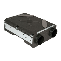
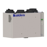
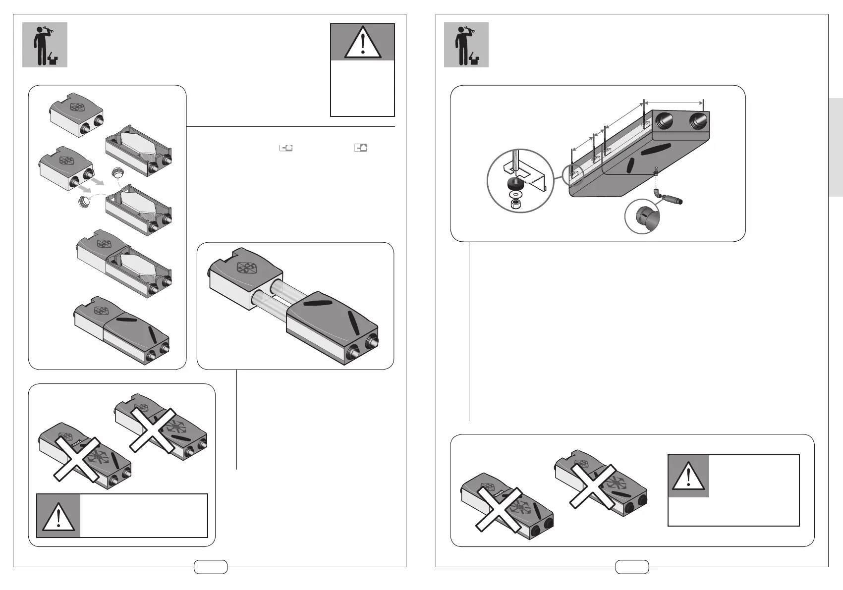
ASSEMBLY
Make sure to respect
the mounting direction
of the ventilation casing.
Direction indicated
using adhesive next
to the connectors
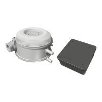
Assembled fitting
Remove the fresh air and
exhaust connectors
from the heat exchanger
Remove the connector seals and place them on the motor casing
connectors
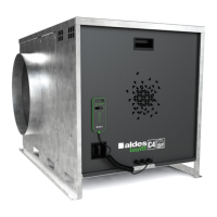
It is possible to link the exchanger to the motor. Fit the brack-
ets onto the motor using 2 screws, the locking system onto the
exchanger and fit the 2 elements together (supplied)
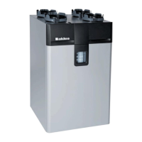
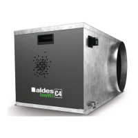
On-line fitting
Facilitates the integration of the exchanger into
the heated space
Used to install the motor in a technical area
(attic, garage...)
To limit the transmission of vibrations, use
flexible ducts or sleeves for aeraulic connections
to the motor casing
After this connection, use preferably rigid ducts
to limit the pressure losses
Prohibited assemblies
Be careful that the direction of the exchanger and
motor are correct! Whether in an assembled or
dissociated configuration, the exchanger and motor
must always be in the same position to each other.
25
CEILING ASSEMBLY
Ceiling mounting
The accessories needed for fitting the casings and condensate evacuation are supplied with the unit
as standard:
Anti-vibration mounts are used to separate the motor from the ceiling to limit the transmission
of noise.
Option: ceiling suspension kit including 4 threaded rods, washers and wall plugs.
Plan for one kit per casing (code 11023117)
Drill a hole in the concrete tile as indicated on the diagram opposite
8 mm)
Screw the condensation water drain nozzle into the exchanger
Assemble the water trap to the bend. This water trap runs without any water.
Be carreful to the direction (arrow)
Prohibited assemblies
Be careful that the direction
of the exchanger and motor are
correct! Whether in an assembled
or dissociated configuration,
the exchanger and motor must
always be in the same position
to each other.