GB
22
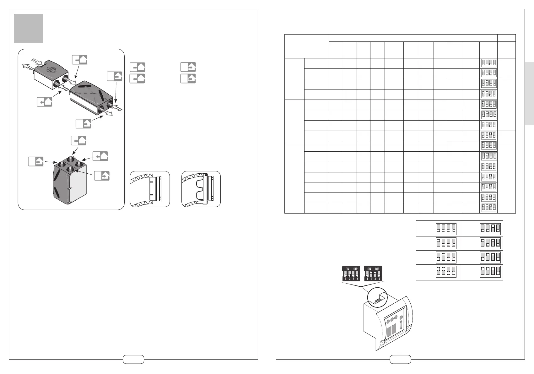
PREPARATIONS FOR INSTALLATION
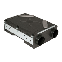
Connectors
tors.
To avoid the nuisance of noise transmission, it is imperative that
connections to the motor casing use flexible couplings: flexible sleeves
or ducts.
For maintenance or replacement access to equipment, there must be
hatches that are large enough to permit access to the equipment or the
technical area
To facilitate the mounting of circular flexible ducts and to ensure that
the network is sealed, each connector is fitted with a 160 mm diameter
quick-fit connector. Insulated ducts must be used once the ducts are in
a non-heated volume (for assembly instructions, see page 30)
Attach the inner duct to
the connector using
a collar.
Attach the insulator and the outer duct
and tighten it with the fixing collar
Make sure the duct is properly fitted
and sealed.
Fresh air intake
Exhaust to outside
Air supply
Air extract
Installation precautions for flexible, insulated ducts:
23
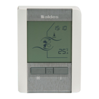
FLOW RATE SELECTION
(Only for the Dee Fly high efficiency version)
The choice of air flow rate is dependant on the number
of ‘wet rooms’ – shown in the table above.
The selection is made be a switch on the back
of the Dee Fly controls. Simply position the jumpers as
shown below to obtain
the required basic
airflow rate:
123 4
123 4
123 4
123 4
123 4
123 4
123 4
123 4
90 m
3
150 m
3
105 m
3
165 m
3
120 m
3
180 m
3
135 m
3
195 m
3
Exhaust Supply
Airflow
kitchen
m
3
/h
Airflow
Bath 1
m
3
/h
Airflow
Bath 2
m
3
/h
Airflow
Bath 3
m
3
/h
Airflow
cellar m
3
/h
Airflow
WC1
m
3
/h
Airflow
WC2
m
3
/h
Airflow
WC3
m
3
/h
Airflow
dressing
m
3
/h
Total
exhaust
airflow
m
3
/h
SWITCH
Position
N° of
grilles
3-room
dwelling
Basic airflow
Kitchen airflow
45
105
30
30
15
15
90
150
4
Basic airflow
Kitchen airflow
45
135
30
30
15
15
15
15
105
195
Basic airflow
Kitchen airflow
45
135
30
30
15
15
15
15
15
15
120
210
5
Basic airflow
Kitchen airflow
45
135
30
30
30
30
15
15
15
15
135
225
4-room
dwelling
Basic airflow
Kitchen airflow
45
135
30
30
30
30
105
195
Basic airflow
Kitchen airflow
45
135
30
30
15
15
15
15
15
15
120
210
Basic airflow
Kitchen airflow
45
135
30
30
30
30
15
15
15
15
135
225
Basic airflow
Kitchen airflow
45
135
30
30
30
30
15
15
15
15
15
15
150
240
6
5 and
more
room
dwelling
Basic airflow
Kitchen airflow
45
135
30
30
30
30
105
195
T5=6
T6=7
T7=8
Basic airflow
Kitchen airflow
45
135
30
30
15
15
15
15
15
15
120
210
Basic airflow
Kitchen airflow
45
135
30
30
30
30
15
15
15
15
135
225
Basic airflow
Kitchen airflow
45
135
30
30
30
30
15
15
15
15
15
15
150
240
Basic airflow
Kitchen airflow
45
135
30
30
30
30
30
30
15
15
15
15
165
255
Basic airflow
Kitchen airflow
45
135
30
30
30
30
30
30
15
15
15
15
15
15
180
270
Basic airflow
Kitchen airflow
45
135
30
30
30
30
30
30
15
15
15
15
15
15
15
15
195
285
(According to the French Building Regulation. Refer to the local Building Regulation to select the airflow.)
1 2 3 4
1 2 3 4
1 2 3 4
1 2 3 4
1 2 3 4
1 2 3 4
1 2 3 4
1 2 3 4
1 2 3 4
1 2 3 4
1 2 3 4
1 2 3 4
1 2 3 4
1 2 3 4
1 2 3 4