INSTALLATION & OPERATIONS GUIDE | MICROSET 4
© Honeywell LT-MS4IOG Rev. 04 | Revised October 2015
12
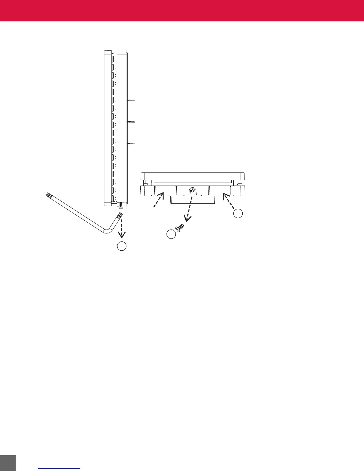
Removing Sensor from wallplate
Figure 6 Removal of Microset 4 from the wallplate.
1. Use a Torx key or screwdriver to loosen the setscrew (if present) on the bottom.
2. Remove the setscrew (if present), but keep it to re-install after the Microset 4 is mounted.
3. Push up the two tabs shown in Figure 6, then pull the bottom of the Microset 4 away from
the wallplate. Lift the Microset 4 from the wallplate.
Mounting the wallplate
See the mounting template in Figure 7.
New Construction
In new construction, rough-in for the Microset 4 is standard 2 in. x 4 in. (50.8 mm x 101.6 mm) single
gang wiring box or a single-gang mud-ring. Skip to Step 6.
Remodel or Retrofit
Use a single-gang old work (or remodel) box or mud ring. Skip to Step 6.
Mount the Microset 4 vertically on the wall.
1. Position and level the wallplate (for appearance only) or use the template in Figure 7.
2. Use a pencil to mark the mounting holes and the wiring opening (dashed line in Figure 7).
3. Cut the wiring opening.
4. Drill two pilot holes in the wall, on your marks.
For drywall, drill 3/16-in. holes.
For plaster or firmer material, drill 7/32-in. holes.