2
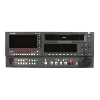
FRONT PANEL OVERVIEW
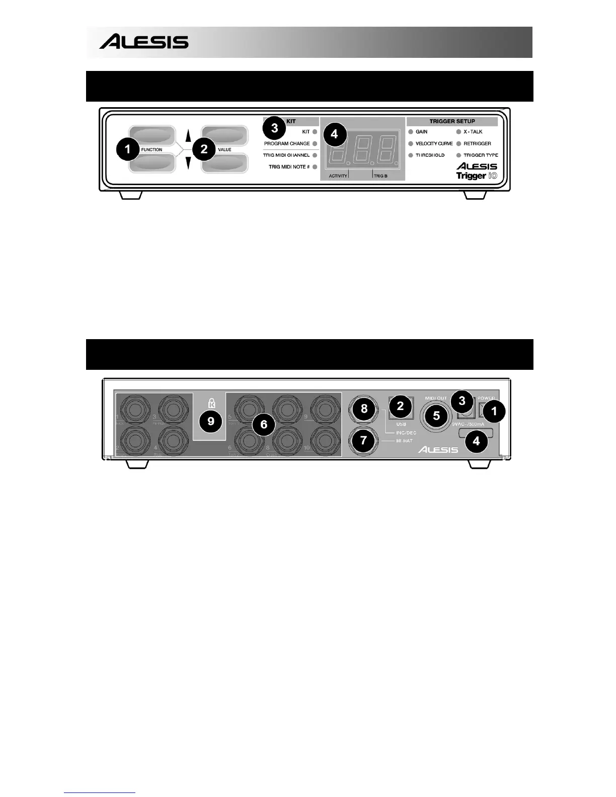
1. FUNCTION UP/DOWN – These buttons are used to select through different functions on the
Trigger IO.
2. VALUE UP/DOWN – These buttons are used to cycle through kits and parameters for the different
functions.
3. FUNCTION LEDs – Each function on the Trigger IO is paired with a corresponding LED on the
panel. These LED will reflect which function is currently being selected.
4. LED SCREEN – The LED screen displays information about the state of the Trigger IO. The
screen also features a small “Activity” LED which will light up each time a trigger generates a Note
On message, as well as a “Trig B” LED which will light up when the secondary zone (ring) of a
dual-zone trigger generates a Note On message.
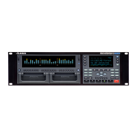
REAR PANEL OVERVIEW
1. Power Button – This button function as a AC/USB power switch. If the button is in the IN
position (AC), the unit will draw power from the connected AC power adapter. If the button is in
the OUT position (USB), the unit will draw power from the USB connection to your computer.
Please note: If your computer’s USB port does not provide sufficient power to the Trigger IO,
please use the included AC adapter to power the unit.
2. USB Port – The USB port is used to transmit MIDI data between the Trigger IO and a computer.
If you are using the USB port, there will be no need for the power adapter to be plugged in – The
Trigger IO will be powered through the USB port.
3. Power Adapter Input – If you do not wish to power the unit through the USB port, please use an
optional AC power adapter to connect the Trigger IO to a power source.
4. Power Adapter Restraint – You can secure the power adapter cord to this restraint to prevent
accidental unplugging.
5. MIDI OUT – Use a five-pin MIDI cable to connect this output to the MIDI IN of an external device,
such as a drum machine, synthesizer or sound module.
6. 10 TRS Trigger Inputs – Please connect your trigger sources to these ten ¼” TRS inputs. You
will notice that some of the inputs are marked. If you would like to take advantage of certain pre-
programmed presets, such as the GM or BFD Lite drum mappings, please follow these markings
to connect your triggers.
7. HI-HAT Input – Please connect your hi-hat pedal to this input.
8. INC/DEC pedal input – Please connect a dual footswitch button to this input. Using this
footswitch input allows you to remotely increment and decrement values from your dual
footswitch.
9. KENSINGTON LOCK – You may use this Kensington lock slot to secure the unit to a table or
surface.