3
HOOKUP DIAGRAM
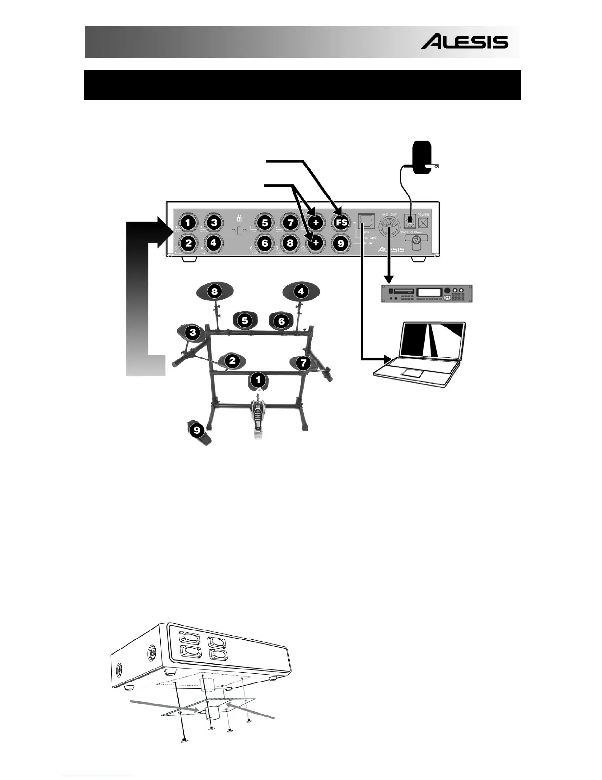
Please study the following diagram to connect your Trigger IO.
POWER ADAPTER
(OPTIONAL)
ATTACH 2 BUTTON FOOTSWITCH HERE
ATTACH ADDITIONAL TRIGGERS HERE
TO EXTERNAL MIDI MODULE
TO COMPUTER
1. Before turning on the Trigger IO, connect all triggers, pads, footswitches, MIDI devices and
external modules as shown above. If you would like to use the Trigger IO with a computer,
connect a USB cord from the Trigger IO to your computer’s USB port.
2. Connect a power source to the Trigger IO. You have two options for powering the Trigger IO:
a. Connect the Trigger IO to a computer’s USB port – the computer’s USB bus will
provide power.
b. Connect an optional 9V AC power adapter to the Trigger IO.
3. Use the power switch on the rear panel of the Trigger IO to turn it on.
Important: Please use the appropriate cables to connect your triggers to the Trigger IO. For
single zone triggers, please use TS cables to connect them to the Trigger IO. If using dual-zone
triggers, please make sure that you are using TRS cables. Using TS cables to connect dual-zone
triggers to the Trigger IO will only allow you to use the primary zone (tip) of the drum.
NARROW
WIDE
The Trigger IO can be mounted on a drum
or cymbal stand and is compatible with
most drum mounts on the market today.
Please attach the drum mount as shown on
the left.
(drum mount not included)