8.6 Drawings 8 Technical Reference
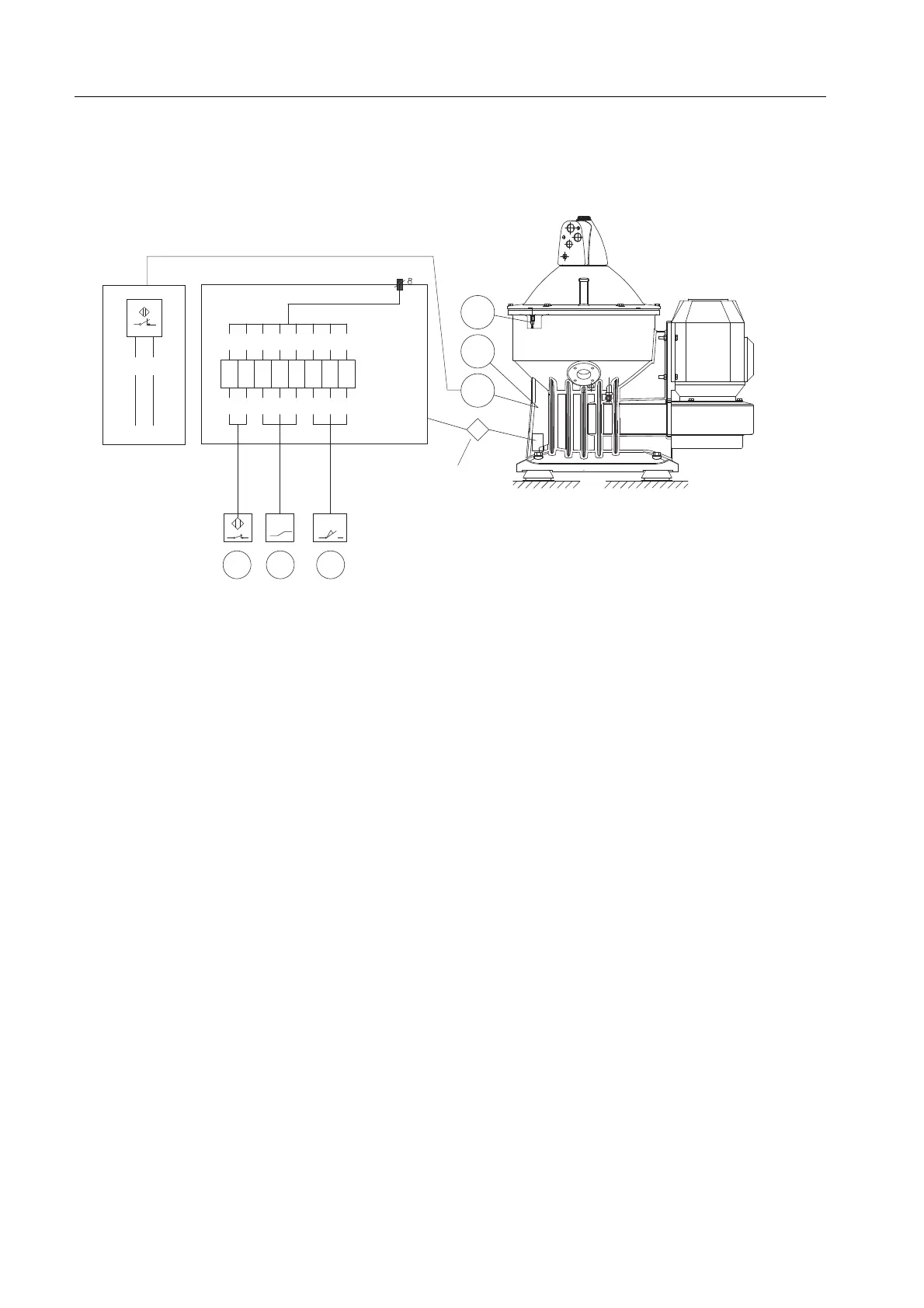
8.6.3 Interconnection diagram
Alfa Laval ref. 561786 Rev. 5
N
752740
J
1
2
3
4
5
6
7
8
BU
BN
BU
BN
BK
GN
RD
BK
RD
BU
GN
YW
WT
BK
BN
PU
X
S
760
760
752
740
1
BU
BN
DC
-
+
A
B
G1019311
A: Wiring without junction box
Wiring of connector “X”:
Wire colour codes:
B: Junction box
740:
Speed sensor, (bowl speed)
752:
Unbalance sensor, (position
trans. for bearing holder)
760:
Interlocking switch (frame top
part)
RD=A
BU=B
GN=C
YW=D
WT=E
BK=F
BN=G
PU=H
BK=Black
BN=Brown
BU=Blue
RD=Red
GN=Green
PU=Purple
YW=Yellow
WT=White
Demand specification wire
Approval:
UL 1007/1569
CSA TR-64
Area acc. to AWG 18
Items showed in this document are not included in all separators. See product specification.
194