10.Remove the touchpad.
11. Remove the keyboard-controller board.
12. Follow the procedure from step 1 to step 16 in Removing the system board.
NOTE: The system board can be removed and installed along with the heat sink. This simplifies the removal and installation
procedure and avoids breaking the thermal bond between the system board and heat sink.
13. Remove the I/O-board.
14. Remove the
power button.
About this task
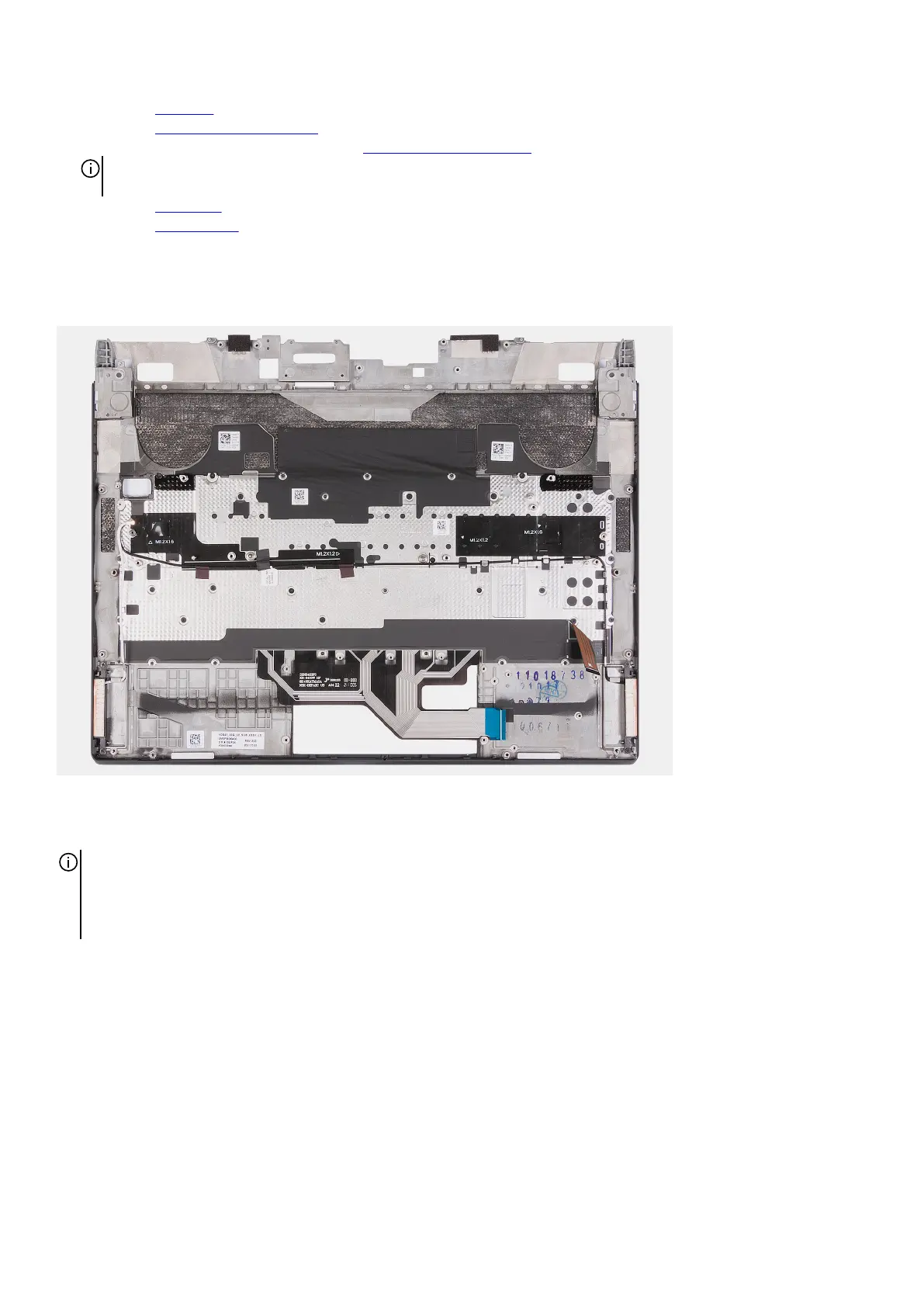
The following image(s) indicate the location of the palm-rest and keyboard assembly and provides a visual representation of the
removal procedure.
Steps
After performing the pre-requisites, you are left with the palm-rest and keyboard assembly.
NOTE: The palm-rest and keyboard assembly includes the following components:
● Palm rest
● Keyboard and keyboard cable
● Wireless antenna (2)
Installing the palm-rest and keyboard assembly
Prerequisites
If you are replacing a component, remove the existing component before performing the installation process.
About this task
The following image(s) indicate the location of the palm-rest and keyboard assembly and provides a visual representation of the
installation procedure.
59