18 / 31
ZYNQ FPGA Development Platform AC7015 User Manual
Amazon Store: https://www.amazon.com/alinx
Sales Email: rachel.zhou@aithtech.com
CP2102GM. The USB interface uses the MINI USB interface. It can be connected
to the USB port of the upper PC with a USB cable for separate power supply and
serial data communication of the core board.
Figure 7-1: USB to Serial Port
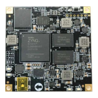
Figure 7-2: USB to Serial Port on the Core Board
Uart Pin Assignment:
Table 7-1: Uart Pin Assignment
Part 8: LED Light
There are 4 red LED lights on the AC7015 core board, one of which is the
power indicator light (PWR), one is the configuration LED light (DONE), two are the
user LED lights (LED1~LED2). When the core board is powered, the power
indicator will illuminate; when the FPGA is configured, the configuration LED will