20 / 31
ZYNQ FPGA Development Platform AC7015 User Manual
Amazon Store: https://www.amazon.com/alinx
Sales Email: rachel.zhou@aithtech.com
LED Pin Assignment:
Table 8-1: LED Pin Assignment
Part 9: Reset Button
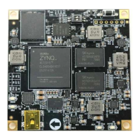
The AC7015 has a reset button RESET and circuitry on the core board. The
reset signal is connected to the PS reset pin of the ZYNQ chip. The reset button
can be used by the user to reset the ZYNQ system. When the reset button is
pressed, the reset chip will generate a low level reset signal to the ZYNQ chip. The
schematic diagram of the reset button and reset chip connection is shown in Figure
9-1:
Figure 9-1: Reset button connection diagram
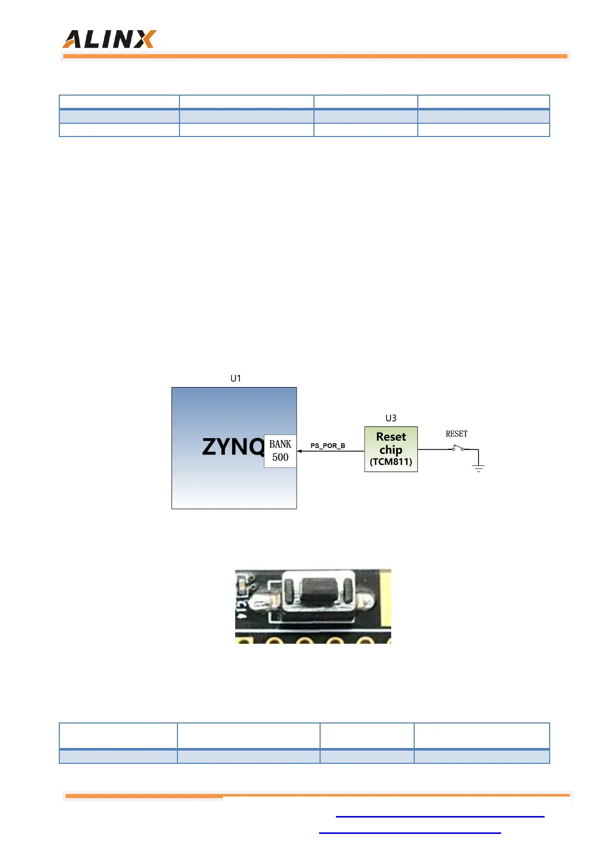
Figure 9-2: Reset button on the Core Board
Reset Pin Assignment:
Table 9-1: Reset Pin Assignment