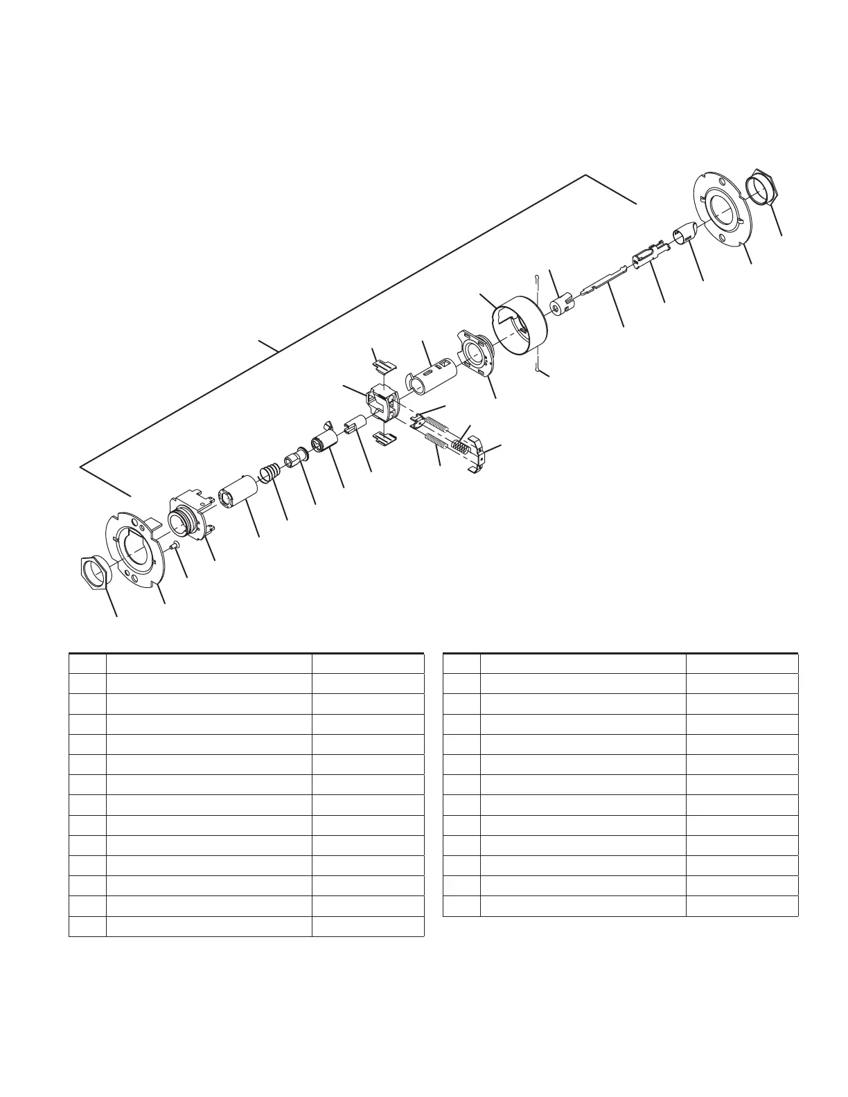
Chassis assemblies
Falcon • T-Series service manual • 19
Entry/oce lock
T511
36
8 (2)
7
11
6
23
13 (2)
1
15
17
18
19
16
3
5
35
24
14
12
10
9 (2)
21
34
4
No. Description Part number
1 Chassis assembly, T511 A30756-000-00
2 Flanged nut (2) 030726-000-30
3 Outer mounting plate 030712-001-30
4 #8-32 x C\,” Self tap screw 031533-006-30
5 Hub and housing assembly A30746-000-00
6 Spindle 030733-000-55
7 Retractor 022106-002-55
8 Retractor insert (2) 022986-001-50
9 Retractor spring (2) 022108-001-60
10 Retractor spring retainer 022112-000-30
11 Hub and plate assembly A30747-000-00
12 Housing case 022114-000-30
13 Cotter pin (2) 002893-000-60
No. Description Part number
14 Inner mounting plate 030712-000-30
15 Spindle, 1 ear, outer 030732-005-30
16 Clutch spring 030709-000-60
17 Clutch driver 030716-001-30
18 Key spindle std 030718-000-30
19 Push actuator 030711-000-30
21 Slide Catch Spring 012107-001-60
23 Dogging Bar 030722-000-30
24 Push/Turn Button Mount 030731-000-30
34 Short Slide Catch 022104-000-30
35 Turn Button Sleeve 022133-000-50
36 Turn Button Cap 030727-000*
 Loading...