12 Rockwell Automation Publication 1606-RM003A-EN-P - March 2019
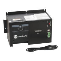
DC-UPS with Integrated Battery - 24V, 10 A
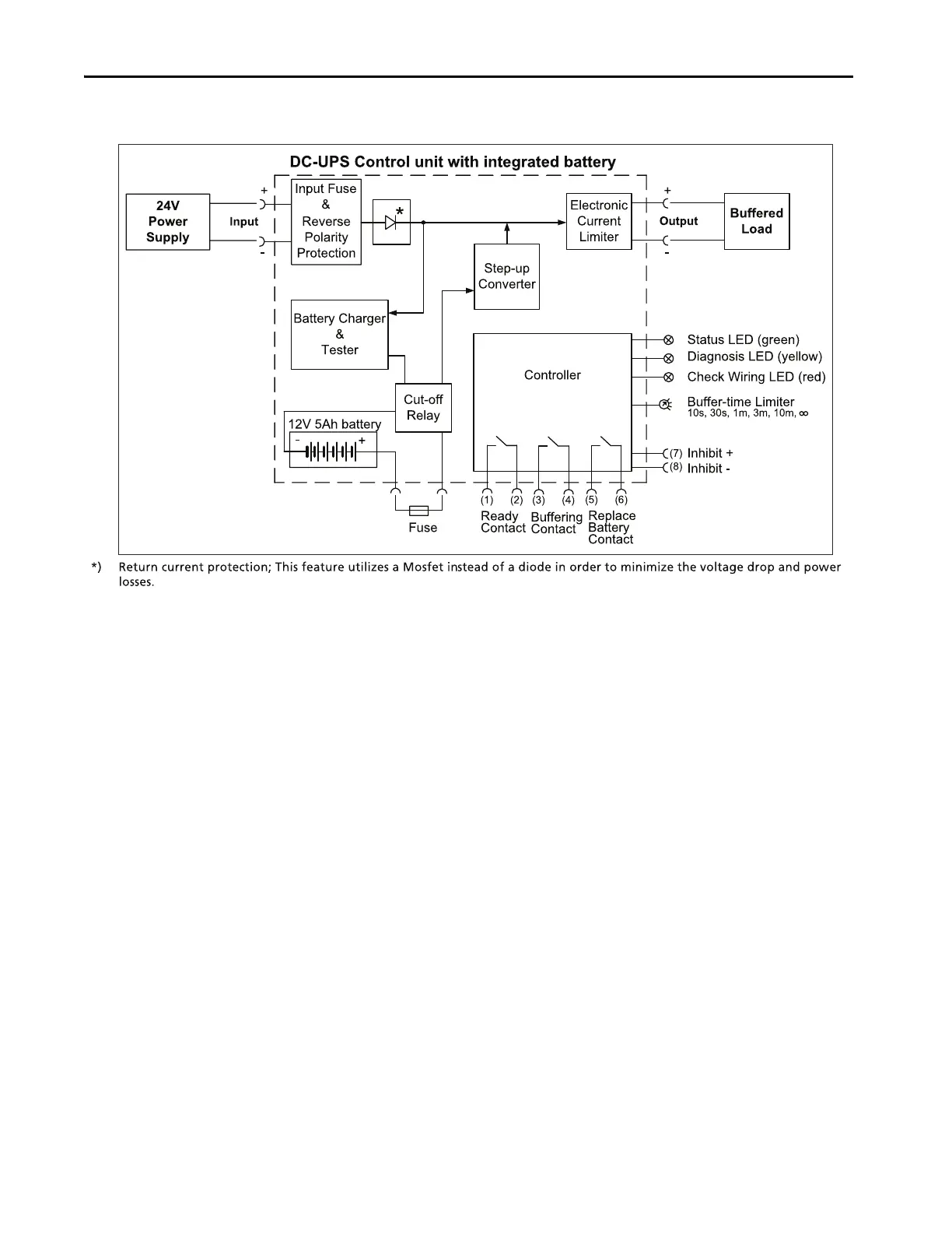
Functional Diagram
Figure 17 - Functional Diagram
Check Wiring and Battery
Quality Tests
The DC-UPS is equipped with an automatic Check Wiring and Battery Quality
test.
Check Wiring Test
Under normal circumstances, an incorrect or bad connection from the battery to
the DC-UPS or a missing (or blown) battery fuse is not recognized by the UPS
when operating in normal mode. Only when backup is required would the unit
not be able to buffer. Therefore, a Check Wiring test is included in the
DC-UPS. This connection is tested every 10 seconds by loading the battery and
analyzing the response from the battery. If the resistance is too high, or the
battery voltage is not in range, the unit displays Check Wiring with the red LED.
At the same time, the green Ready LED turns off.
 Loading...