16 Rockwell Automation Publication 1606-RM003A-EN-P - March 2019
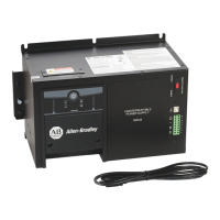
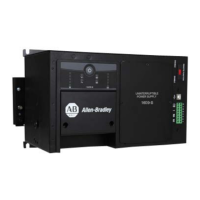
DC-UPS with Integrated Battery - 24V, 10 A
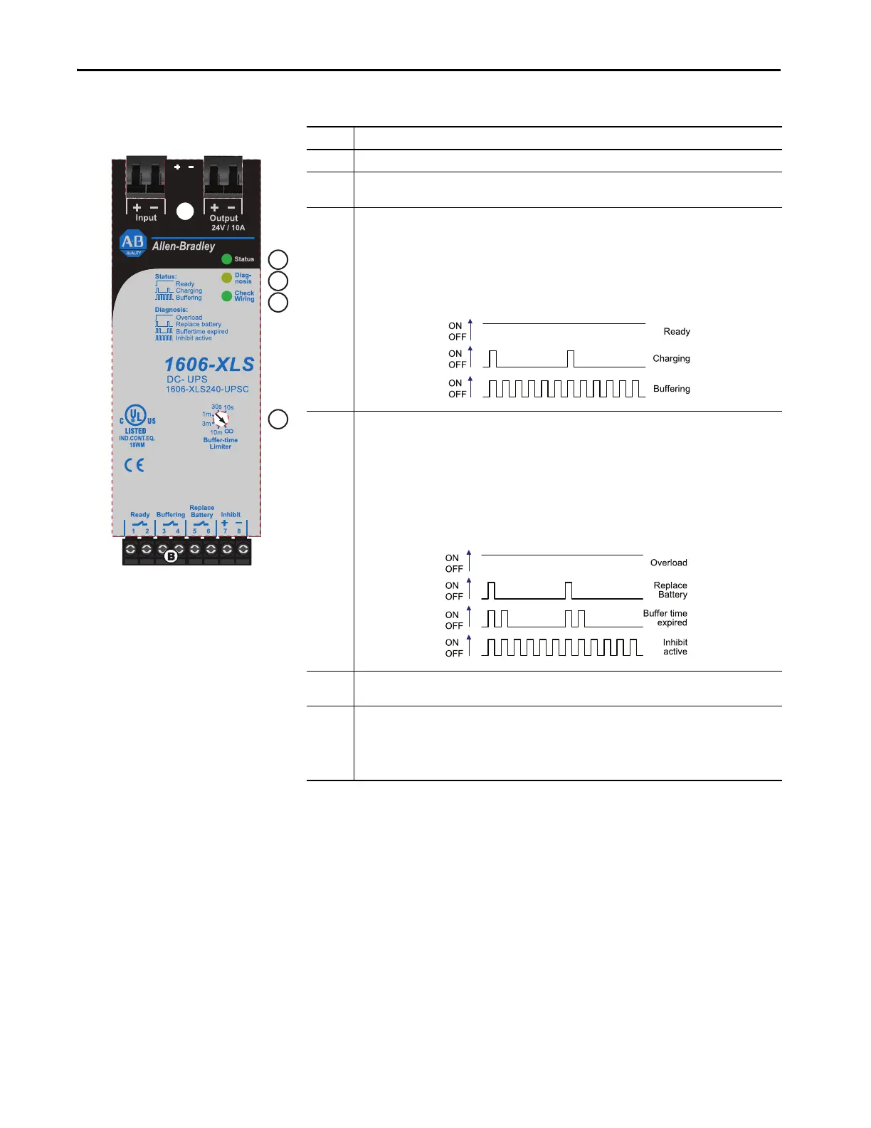
Front Side and User
Elements
Letter Definition
A Power port - Quick-connect spring-clamp terminals, connection for input voltage and output voltage.
BSignal port - Plug connector with screw terminals, which are inserted from the bottom. Connections for
the Ready, Buffering, Replace Battery relay contacts and for the Inhibit input.
C Green Status LED -
Ready: Battery is charged > 85%, no wiring failures are recognized, input voltage is sufficient and inhibit
signal is not active.
Charging: Battery is charging and the battery capacity is below 85%.
Buffering: Unit is in buffer mode.
Figure 19 - Green LED Flashing Pattern
D Yellow Diagnosis LED -
Overload: Output has switched off due to long overload in buffer mode or due to high temperatures.
Replace battery: Indicates a battery that failed the battery quality test (SoH test). The battery should be
replaced as soon as possible.
Buffer-time expired: Output has switched off due to settings of Buffer- timer Limiter. This signal is
displayed for 15 minutes.
Inhibit active: Indicates that buffering is disabled due to an active inhibit signal.
Figure 20 - Yellow Diagnostic LED
E Red Check Wiring LED - This LED indicates a failure in the installation (for example too low input voltage),
wiring, battery, or battery fuse.
F Buffer-time Limiter - The dial limits the maximum buffer time in a buffer event to save battery energy.
When the battery begins to recharge after a discharging event, the process is completed much faster since
only the energy, which was taken out of the battery, needs to be replenished. Buffering durations include
10 s, 30 s, 1 minute, 3 minutes, 10 minutes, and infinity (until the battery is discharged) which allows
buffering until the deep discharge helps protect stops buffering.
 Loading...