Rockwell Automation Publication 1734-UM013N-EN-P - September 2017 127
Configure the Module for a SmartGuard Controller Chapter 6
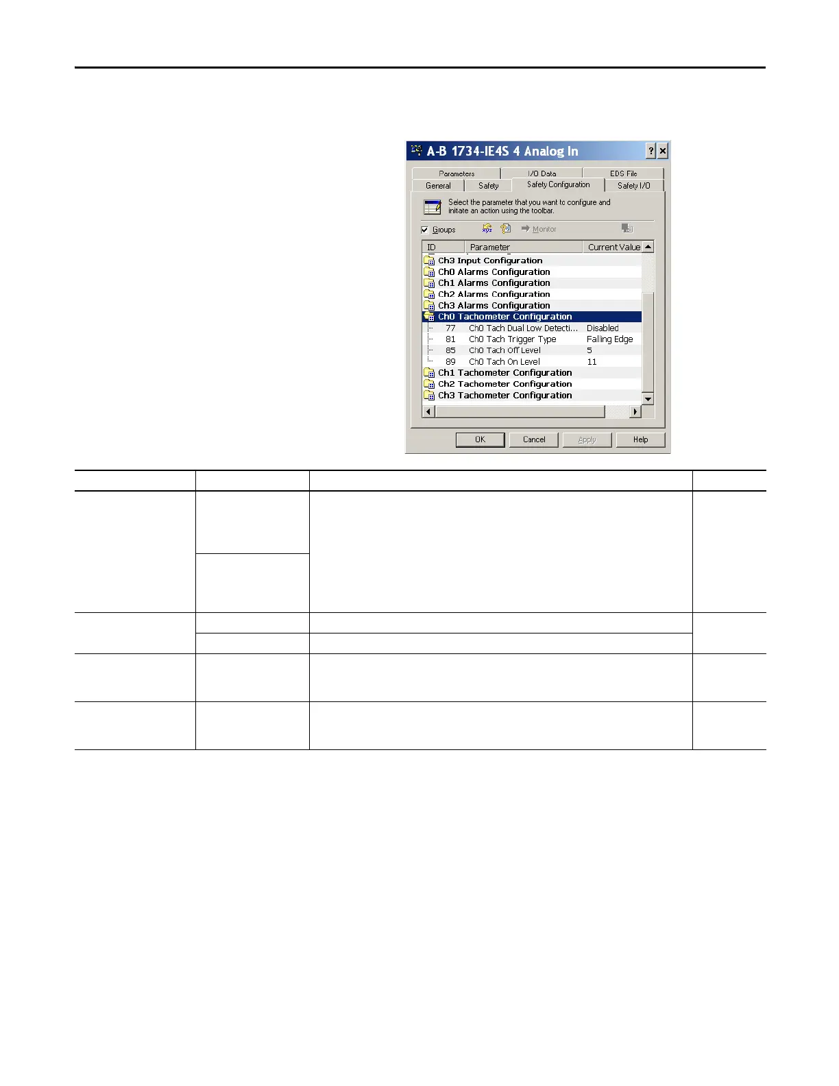
6. To display parameters for editing, double-click each Channel Tachometer
Configuration group.
Parameter Name Value Description Default
Tach Dual Low Detection On To increase the diagnostic coverage of your speed sensing loop, you must determine whether the
two tachometer sensors you are using to sense speed are shorted together. That is, you must be able
to detect a channel-to-channel fault. One method is to implement two tachometer sensors so that,
during normal operation, their pulse trains are never low simultaneously. When Dual Low Detection
is enabled, the module detects this condition as a fault, which indicates that the two sensors are
shorted together.
To use this feature, you must use Channels 0 and 1 together, and Channels 2 and 3 together.
Channels 0 and 1 have the same setting and channels 2 and 3 have the same setting. Both channels
in the pair must use tachometer mode and the dual low detection diagnostic.
Disabled
Off
Tach Trigger Type Falling edge (NPN) Non-inverted input signal. Falling edge
Rising edge (PNP) Inverted input signal.
Tach Off Level 0…23V
(in 1 V increments)
This value is the voltage at which the module considers the tachometer sensor to be OFF for
tachometer speed calculation purposes.
The Tachometer Off Level must be less than the Tachometer On Level.
5V
Tach On Level 1…24V
(in 1 V increments)
This value is the voltage at which the module considers the tachometer sensor to be ON for
tachometer speed calculation purposes.
The Tachometer On Level must be greater than the Tachometer Off Level.
11V
 Loading...


