Rockwell Automation Publication 1734-UM013N-EN-P - September 2017 73
Install the Module Chapter 4
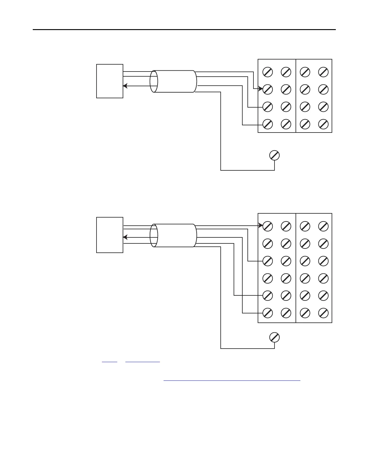
Figure 37 - 3-wire Current Sensor (SIL 2)
Figure 38 - 4-wire Voltage or Tachometer Sensor (SIL 2)
Follow the Guidelines for Wiring Safety Analog Inputs on page 71.
V0 V1 V2 V3
I0 I1 I2 I3
COM COM COM COM
S0
FE
S1 S2 S3
For 0…20 mA analog current-output sensors, the signal levels for operation for the application must be outside the signal level when the signal
is not present, for example, when the wire is broken.
SIL 2
3-wire
Sensor
1734-TB Terminal Bases
Signal (I)
+24V
Cable Shield
Signal Return
FE
V0 V1 V2 V3
I0 I1 I2 I3
COM COM COM COM
COM COM COM COM
S0 S1 S2 S3
S0 S1 S2 S3
Signal Return and Common are at the same potential.
See Figure 47
and Figure 48 on page 78 for tachometer wiring detail.
SIL 2
4-wire
Sensor
1734-TOP3 Terminal Bases
Signal (V)
+24V
Cable Shield
Signal Return
Common
 Loading...


