74 Rockwell Automation Publication 1734-UM013N-EN-P - September 2017
Chapter 4 Install the Module
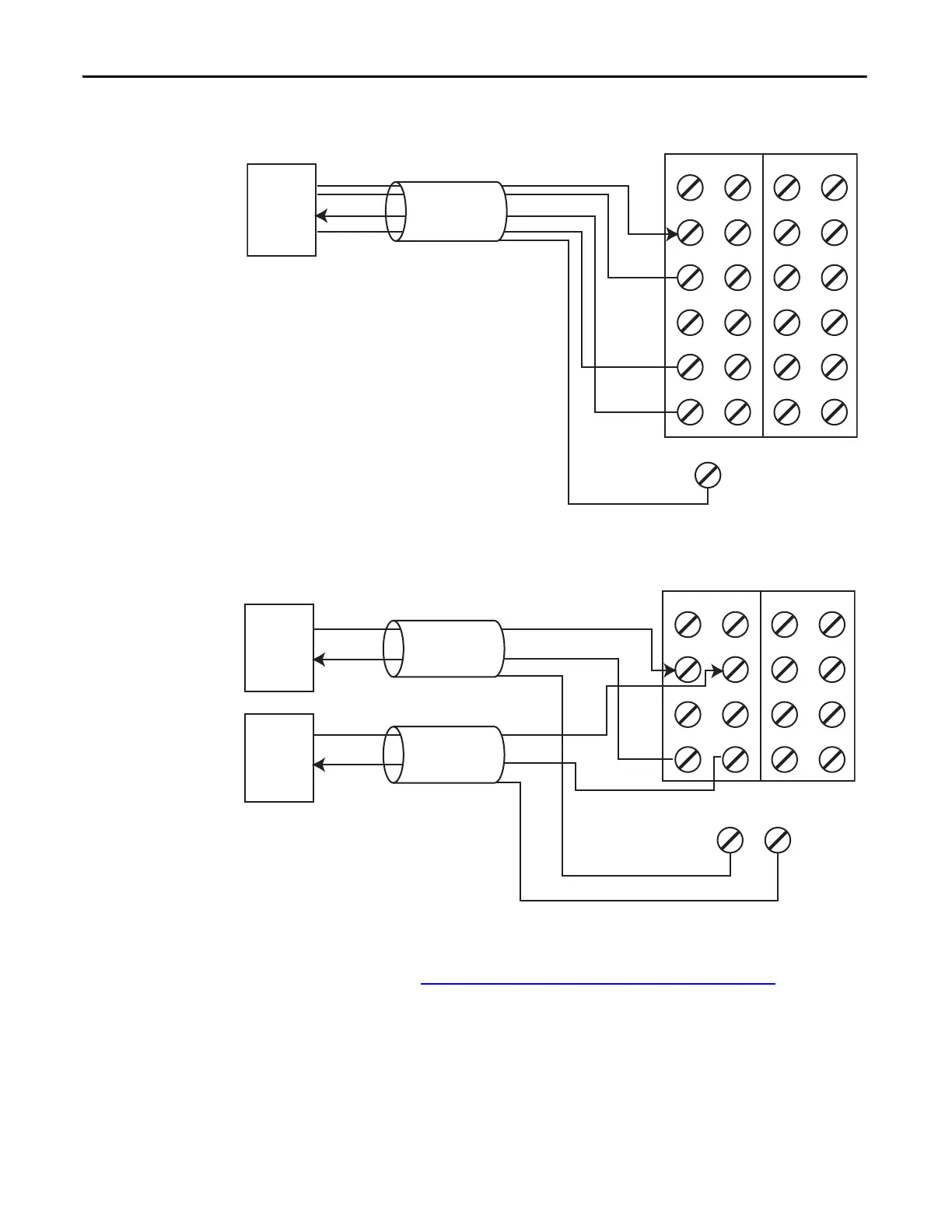
Figure 39 - 4-wire Current Sensor (SIL 2)
Figure 40 - 2-wire Current (4…20 mA) Sensor (SIL 3)
Follow the Guidelines for Wiring Safety Analog Inputs on page 71.
FE
V0 V1 V2 V3
I0 I1 I2 I3
COM COM COM COM
COM COM COM COM
S0 S1 S2 S3
S0 S1 S2 S3
Signal Return and Common are at the same potential.
SIL 2
4-wire
Sensor
1734-TOP3 Terminal Bases
Signal (I)
+24V
Cable Shield
Signal Return
Common
V0 V1 V2 V3
I0 I1 I2 I3
COM COM COM COM
S0
FE
S1 S2 S3
FE
Field sensors are monitoring the same signal in a redundant configuration.
You must configure a safety deadband between the two signals to achieve SIL 3.
SIL 2
2-wire
Sensor
1734-TB Terminal Bases
Signal (I)
+24V
Cable Shield
Cable Shield
+24V
SIL 2
2-wire
Sensor
Signal (I)
 Loading...


