Rockwell Automation Publication 1734-UM013N-EN-P - September 2017 75
Install the Module Chapter 4
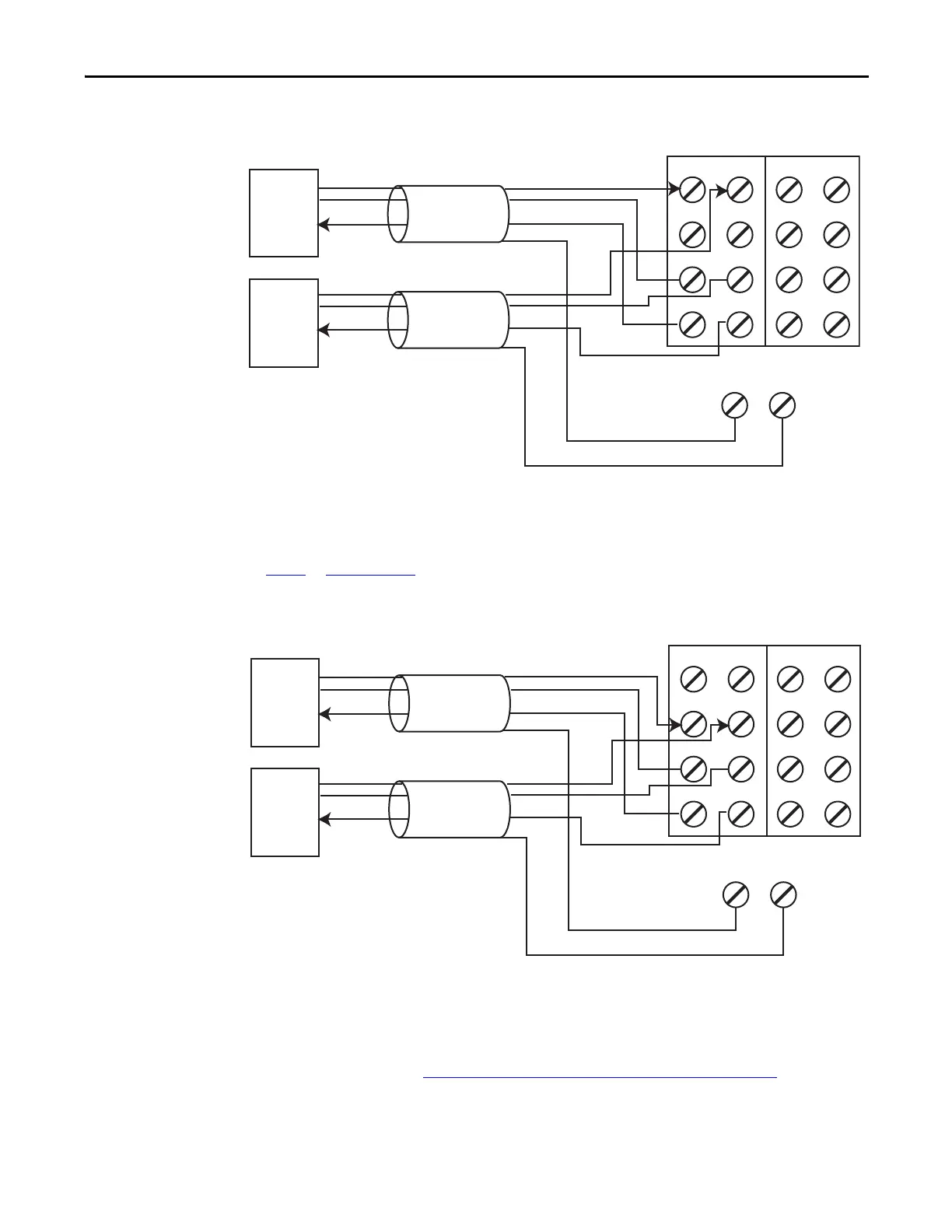
Figure 41 - 3-wire Voltage or Tachometer Sensor (SIL 3)
Figure 42 - 3-wire Current Sensor (SIL 3)
Follow the Guidelines for Wiring Safety Analog Inputs on page 71.
V0 V1 V2 V3
I0 I1 I2 I3
COM COM COM COM
S0
FE
S1 S2 S3
FE
This wiring configuration can also be used for SIL 2 redundant Tachometer mode.
For analog voltage-output sensors, the signal levels for operation for the application must be outside the signal level when the signal is not
present, for example, when the wire is broken.
Field sensors are monitoring the same signal in a redundant configuration.
You must configure a safety discrepancy deadband between the two signals to achieve SIL 3.
SIL 2
3-wire
Sensor
1734-TB Terminal Bases
Signal (V)
+24V
Cable Shield
Cable Shield
+24V
SIL 2
3-wire
Sensor
Signal (V)
Signal Return
Signal Return
See Figure 47
and Figure 48 on page78 for tachometer wiring detail.
V0 V1 V2 V3
I0 I1 I2 I3
COM COM COM COM
S0
FE
S1 S2 S3
FE
For 0…20 mA analog current-output sensors, the signal levels for operation for the application must be outside the signal level when the signal
is not present, for example, when the wire is broken.
Field sensors are monitoring the same signal in a redundant configuration.
You must configure a safety discrepancy deadband between the two signals to achieve SIL 3.
SIL 2
3-wire
Sensor
1734-TB Terminal Bases
Signal (I)
+24V
Cable Shield
Cable Shield
+24V
SIL 2
3-wire
Sensor
Signal (I)
Signal Return
Signal Return
 Loading...


